In the FAD assessment of the four A533B welded-plate problems , the residual stress intensity factor for the as-welded case, $K_I^S \approx 46\ \mathrm{MPa\cdot m^{0.5}}$, has always been entered directly: FITNET obtained it by integrating the measured residual stress profile, and we simply fed that ready-made number into the vertical coordinate $K_r$.
A natural follow-up question: how does that 46 actually emerge from a residual stress curve, and can it be computed with Annex M?
It can. This is exactly what the BS 7910 Annex M.4.2 solution (finite-plate surface flaw, polynomial stress) does: given a stress polynomial $\sigma(x)$ distributed through the wall thickness, it integrates that stress along the crack front with a weight function to obtain the stress intensity factor of the crack. In this post we run that single step with the Annex M calculator in mechCalc, integrating the as-welded residual profile into the deepest-point SIF, and then compare it with the 46 from FITNET. This is a pure single-point stress intensity factor calculation, independent of any FAD assessment.
Principle: polynomial stress profile → SIF
The flaw being assessed is a semi-elliptical surface crack in the weld region (depth $a$, surface half-length $c$). The secondary stress (welding residual) is not constant through the wall thickness but follows a curve, which BS 7910 describes with a polynomial of degree up to five (the coordinate $x$ is measured from the cracked surface and normalised by the wall thickness $B$):
$$ \sigma(x) = \sum_{n=0}^{5} \sigma_n \left(\frac{x}{B}\right)^n $$The deepest-point $K_I$ is assembled per Eq. M.13 of Annex M.4.2.2: each stress order is paired with a Fett geometry function $f_i^d$ (read from Table M.1, with bilinear interpolation over $a/B$ and $a/2c$), and the sum is multiplied by $\sqrt{\pi a}$:
$$ K_I = \sqrt{\pi a}\,\sum_{i=0}^{5} \sigma_i \left(\frac{a}{B}\right)^{i} f_i^{\,d}\!\left(\frac{a}{B},\ \frac{a}{2c}\right) $$Source: BS 7910:2019, Annex M.4.2.2, Eq. M.13, Table M.1 (deepest point) / Table M.2 (surface point); geometry functions taken from Fett & Munz (1997) [M.10] and Fett, Munz & Neumann (1990) [M.11].
The key point: this solution’s polynomial convention is precisely $\sigma_n(x/B)^n$ (normalised by wall thickness, $x$ measured from the cracked surface). The A533B measured residual profile is already given in terms of $x/t$ (with $t=B$), so the coefficients map term by term with no change of variable needed.
Inputs: the A533B as-welded residual profile
The as-welded (LLAW / HLAW) measured residual stress profile given in §2.2 of the overview post (transverse to the weld, for the $x/t \le 0.5$ range, which covers $a/t=0.273$):
$$ \sigma^*(x/t) = -108.35 + 3543.6\,(x/t) - 9871.5\,(x/t)^2 + 2930.3\,(x/t)^3 \quad [\mathrm{MPa}] $$Mapping each term onto the Annex M.4.2 polynomial coefficients, and taking the crack and plate geometry of the LLAW as-welded specimen:
| Parameter | Value | Note |
|---|---|---|
| Crack depth $a$ | 19.4 mm | LLAW as-welded pre-crack depth |
| Crack surface half-length $c$ | 87.5 mm | Full length $2c = 175$ mm |
| Plate thickness $B = t$ | 71 mm | $a/B = 0.273$, within the Fett table grid |
| Section width $W$ | 600 mm | Finite-width correction |
| $\sigma_0$ | −108.35 MPa | Surface ($x=0$) residual stress, compressive |
| $\sigma_1$ | 3543.6 MPa | First-order term |
| $\sigma_2$ | −9871.5 MPa | Second-order term |
| $\sigma_3$ | 2930.3 MPa | Third-order term |
| $\sigma_4,\ \sigma_5$ | 0 | The profile is a cubic polynomial |
Try it yourself: entering it in the calculator
One click: open this example in the calculator . The inputs are filled in for you. You can also pick “FITNET A533B residual profile — K_I^S from Annex M.4.2” from the “Verification examples” list at the top of the calculator. The steps below are for checking or entering the inputs by hand.
Open the BS 7910 Annex M stress intensity factor calculator in mechCalc and set up three cards:
- 1. Crack Type & Flaw Geometry: set “1. Geometry Group” to
Flat Plateand “2. Flaw Type” toM.4.2 · Finite Surface, Polynomial Stress [Fett]— this is the finite surface flaw solution under a polynomial stress profile; enter crack depth $a$ = 19.4 and crack surface half-length $c$ = 87.5. - 2. Component Geometry: wall / plate thickness 71, total section width 600.
- 3. Stress & Polynomial Coefficients: polynomial $\sigma_0..\sigma_3$ as in the table above ($\sigma_4=\sigma_5=0$).
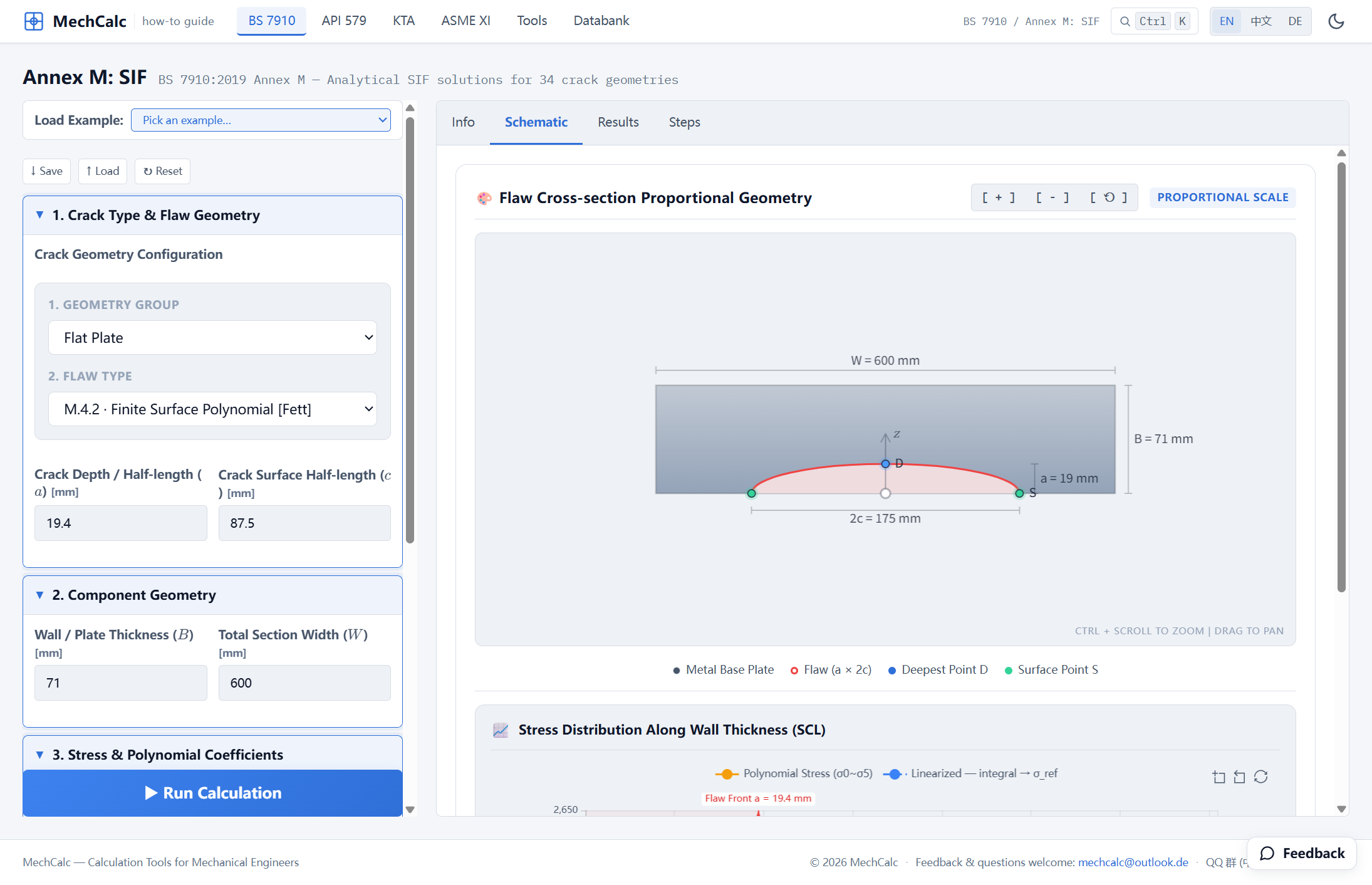 Figure 1: Selecting “M.4.2 · Finite Surface, Polynomial Stress [Fett]” in the Annex M calculator and entering the A533B as-welded residual stress polynomial. The “Flaw Cross-section Proportional Geometry” panel on the Schematic tab draws the crack to scale: a semi-elliptical surface crack (red) of depth a=19.4 mm and full length 2c=175 mm on a W=600 mm wide plate, with the deepest point D and surface point S marked.
The calculator also draws this residual stress distribution through the wall thickness in real time and to scale — this is exactly the quantity being integrated:
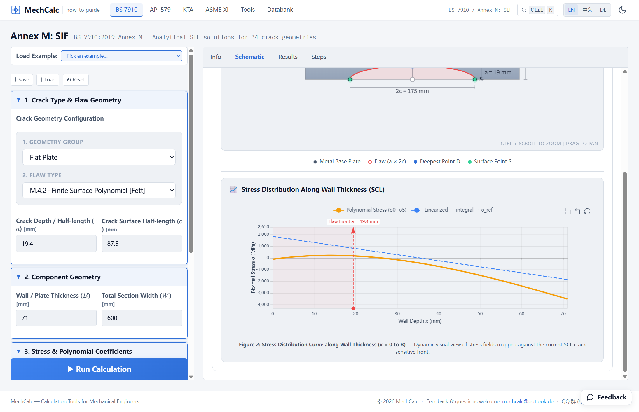 Figure 2: The “Stress Distribution Along Wall Thickness (SCL)” chart: residual stress through the wall thickness (orange line, polynomial σ₀~σ₅). The surface (x=0) is in compression at −108 MPa, turns rapidly to tension with depth, and peaks in the mid-thickness region; the dashed red vertical line marks the crack-front position at a=19.4 mm. The dashed blue line is the linearized equivalent (membrane + bending). The deepest-point K_I is the result of integrating this curve over [0, a] along the crack front with the weight function.
Results
Click Run Calculation to obtain the SIF at the two crack-front points:
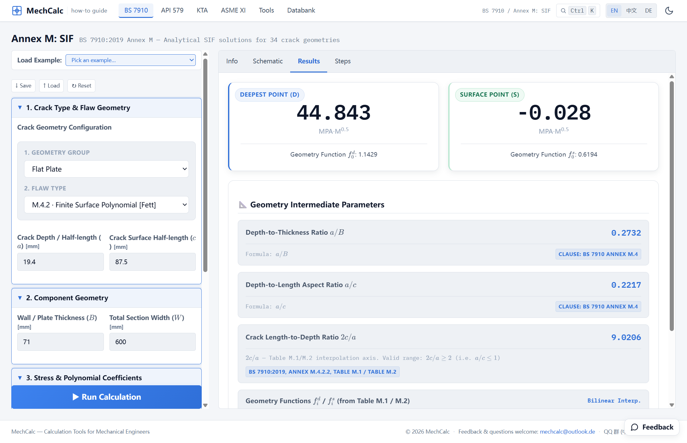 Figure 3: Annex M.4.2 results. Deepest point D: K_I = 44.843 MPa·m^0.5 (geometry function f₀ᵈ=1.1429); surface point S: K_I ≈ −0.028 ≈ 0. Below are the intermediate quantities a/B=0.2732, a/c=0.2217, 2c/a=9.0206, with the source cited as BS 7910 Annex M.4.2.2 Table M.1/M.2.
| Crack-front point | $K_I$ [MPa·m$^{0.5}$] | Note |
|---|---|---|
| Deepest point D | 44.843 | The residual $K_I^S$ for the deepest-point assessment point on the FAD |
| Surface point S | −0.028 (≈ 0) | Near-surface compression, net contribution almost zero; taken as 0 for the surface-point assessment point on the FAD |
Why is the surface point almost zero? The surface-point geometry function weights the near-surface region most heavily, and there the residual stress is compressive (−108 MPa at $x=0$); compressive stress contributes negatively to the opening-mode SIF and just cancels the small amount of tension in the shallow layer, leaving net $K_I \approx 0$. The deepest point, by contrast, sees the large band of tension in the mid-thickness region, and so integrates out to 44.8 MPa·m$^{0.5}$.
Both values go into the FAD: the fracture assessment calculator assesses a semi-elliptical surface flaw at the deepest point and at the surface point, and the flaw is not acceptable if either point is not acceptable (by analogy with BS 7910:2019+C1:2025 B.5.6). A directly entered $K_I^S$ therefore also has a deepest-point field and a surface-point field. The deepest point takes 46 (the four problems keep the FITNET value, see the next section); the surface-point integral is negative, and when $K_I^S<0$ both $K_I^S$ and $\rho$ are set to 0 (BS 7910:2019, §7.3.6), so the surface point takes 0.
Whitebox: term-by-term expansion of Eq. M.13
The Whitebox steps in the calculator lay out the deepest-point summation in full ($a=0.0194$ m):
$$ K_I = \sqrt{\pi a}\,\big[\underbrace{-108.35{\times}1.0000{\times}1.1429}_{\sigma_0\text{ term}} + \underbrace{3543.6{\times}0.2732{\times}0.6585}_{\sigma_1\text{ term}} + \underbrace{-9871.5{\times}0.0747{\times}0.4820}_{\sigma_2\text{ term}} + \underbrace{2930.3{\times}0.0204{\times}0.3873}_{\sigma_3\text{ term}}\big] = 44.84 $$Here the Fett geometry functions (Table M.1, deepest point), obtained by bilinear interpolation at $a/B=0.273$ and $2c/a=9.02$, are $f_0^d{=}1.1429,\ f_1^d{=}0.6585,\ f_2^d{=}0.4820,\ f_3^d{=}0.3873$. Every step traces back to a table in the standard — no black box.
Comparison with the FITNET value
Here is the residual $K_I^S$ computed above next to the value reported by FITNET:
| Quantity | mechCalc (Annex M.4.2) | FITNET | Difference |
|---|---|---|---|
| Deepest-point residual $K_I^S$ [MPa·m$^{0.5}$] | 44.84 | ≈ 46 | −2.5% |
A 2.5% difference — good agreement between two different solutions. mechCalc uses the Fett tabulated geometry functions of BS 7910 Annex M.4.2; FITNET uses the solution of reference [13.6] (Sharples & Clayton) for a semi-elliptical surface crack in a plate under distributed loading (FITNET FFS Procedure MK7 (2006), Vol. II §13.2.5, Table 13.9 step 9). For the same physical quantity computed with different solutions, a difference of a few percent is normal, and here the mechCalc value is slightly lower.
What matters here is this: the deepest-point $K_I^S=46$ that the four-problem FAD assessment takes as a direct input can be worked out from the raw residual stress profile with the Annex M.4.2 solution, to within −2.5% of the FITNET value. So when you have your own measured profile, you need not rely on a value from the literature; you can integrate it yourself.
Note: the −2.5% is a normal difference between two different solutions for the same physical quantity. To keep the residual term the same on both sides, the four FAD problems still use the direct $K_I^S$ value from the FITNET source.
Source: the FITNET project’s Case Studies for Fracture, case “A533B-1 Steel Residual Stress Experiments” (FITNET FFS Procedure MK7 (2006), Vol. II §13.2.5); original test report C C France, J K Sharples & C Wignall, AEA Technology Report AEAT-4236 (SINTAP/TASK4/AEAT18, 1998). The SIF solution follows BS 7910:2019+C1:2025, Annex M.4.2.2 (Eq. M.13, Table M.1/M.2).
🧮 Online calculator: BS 7910 Annex M Stress Intensity Factor Calculator — Try it yourself: set Geometry Group to Flat Plate, Flaw Type to M.4.2 · Finite Surface, Polynomial Stress [Fett], enter a=19.4, c=87.5, B=71, W=600, and the polynomial σ₀=−108.35, σ₁=3543.6, σ₂=−9871.5, σ₃=2930.3 to obtain the deepest-point K_I=44.84 MPa·m^0.5.
Verification manual for this calculator: BS 7910 Fracture Assessment Calculator verification manual