This is the third of four problems on the welded A533B-1 plate. The first two both sat in the low load-ratio brittle-fracture regime and compared residual stress; this one shifts the battlefield — to the high load-ratio, large-plasticity regime.
For the shared background and method behind all four problems, see the overview post BS 7910 FAD Assessment: What Residual Stress Does, Seen Through a FITNET Case .
What this problem asks
HLAW = High-$L_r$ + as-Welded: as-welded condition, assessment temperature raised to −30 ℃, load increased into the high load-ratio regime. The warmer temperature lifts the fracture toughness somewhat off the lower shelf ($K_{mat}=62\ \mathrm{MPa\cdot m^{0.5}}$), while the load is raised to a failure load of 5.10 MN. The residual stress stays the as-welded value ($K_I^S=46$).
The question becomes: once plasticity has developed extensively in the high-$L_r$ regime, does that residual stress — so dominant in the low-temperature regime — still call the shots?
Principle: once L_r crosses the cut-off, the assessment is governed by plastic collapse
The assessment is still BS 7910:2019 §7.3.3 Option 1, but this problem triggers the FAD’s plastic cut-off mechanism. BS 7910:2019 §7.3.2, Eq. 7.25 defines a cut-off value to prevent the net section from collapsing plastically before fracture occurs:
$$ L_{r,max} = \frac{\sigma_Y + \sigma_U}{2\sigma_Y} $$When the assessment point’s abscissa reaches $L_r \ge L_{r,max}$, the failure assessment line takes $f(L_r)=0$ (§7.3.3 Eq. 7.28) — meaning that however low the ordinate, the flawed structure is not acceptable because of plastic collapse / net-section yielding. Here $\sigma_Y=520$ and $\sigma_U=677$, which gives $L_{r,max}\approx 1.15$.
In addition, BS 7910 Annex R sets the plasticity interaction $\rho = 0$ for $L_r \ge 1.05$ (BS 7910:2019, Annex R, Eq. R.2); here $L_r$ is far above 1.05, so $\rho$ is taken as 0.
As usual, both points of the semi-elliptical surface flaw are assessed, the deepest point and the surface point (see “The principle in brief” in Problem 1 ). Both points share the same $L_r$, so when $L_r \ge L_{r,max}$ both are judged as plastic collapse together.
Inputs at a glance
| Parameter | Value | Note |
|---|---|---|
| Crack depth $a_0$ / half-length $c_0$ | 19.0 / 87 mm | Full length $2c_0=174$ mm |
| Thickness $B=t$ / width $W$ | 70 / 600 mm | |
| Primary membrane $P_m$ / bending $P_b$ | 0 / 1015 MPa | Pure bending (elastic conversion of the 5.10 MN fracture load) |
| Yield $\sigma_Y$ / tensile $\sigma_U$ | 520 / 677 MPa | $L_{r,max}\approx 1.15$ |
| Fracture toughness $K_{mat}$ | 62 MPa·m$^{0.5}$ | As-welded weld @ −30 ℃ |
| Residual $K_I^S$ (direct input, deepest / surface point) | 46 / 0 MPa·m$^{0.5}$ | Same as LLAW (as-welded); the surface value is negative, so 0 is used |
Try it yourself: entering it in the calculator
One click: open this example in the calculator . The inputs are filled in for you. You can also pick “FITNET A533B residual stress — HLAW (as-welded, high load)” from the “Verification examples” list. The steps below are for checking or entering the inputs by hand.
The steps match Problem 1
: pick Option 1 in the “Assessment Option (FAD)” card, then fill in each card. Use the HLAW values from the “Inputs at a glance” table above: crack depth 19.0 and crack half-length 87; wall thickness 70; primary bending stress $P_b=1015$; yield strength 520 and tensile strength 677; fracture toughness $K_{mat}=62$; set “Secondary (residual/thermal) load” to Enter K_I^S directly and enter 46 at the deepest point and 0 at the surface point. Leave the plasticity interaction ($\rho$) source at the default Annex R (calculated) — default (Annex R gives 0 automatically for $L_r \ge 1.05$).
Results
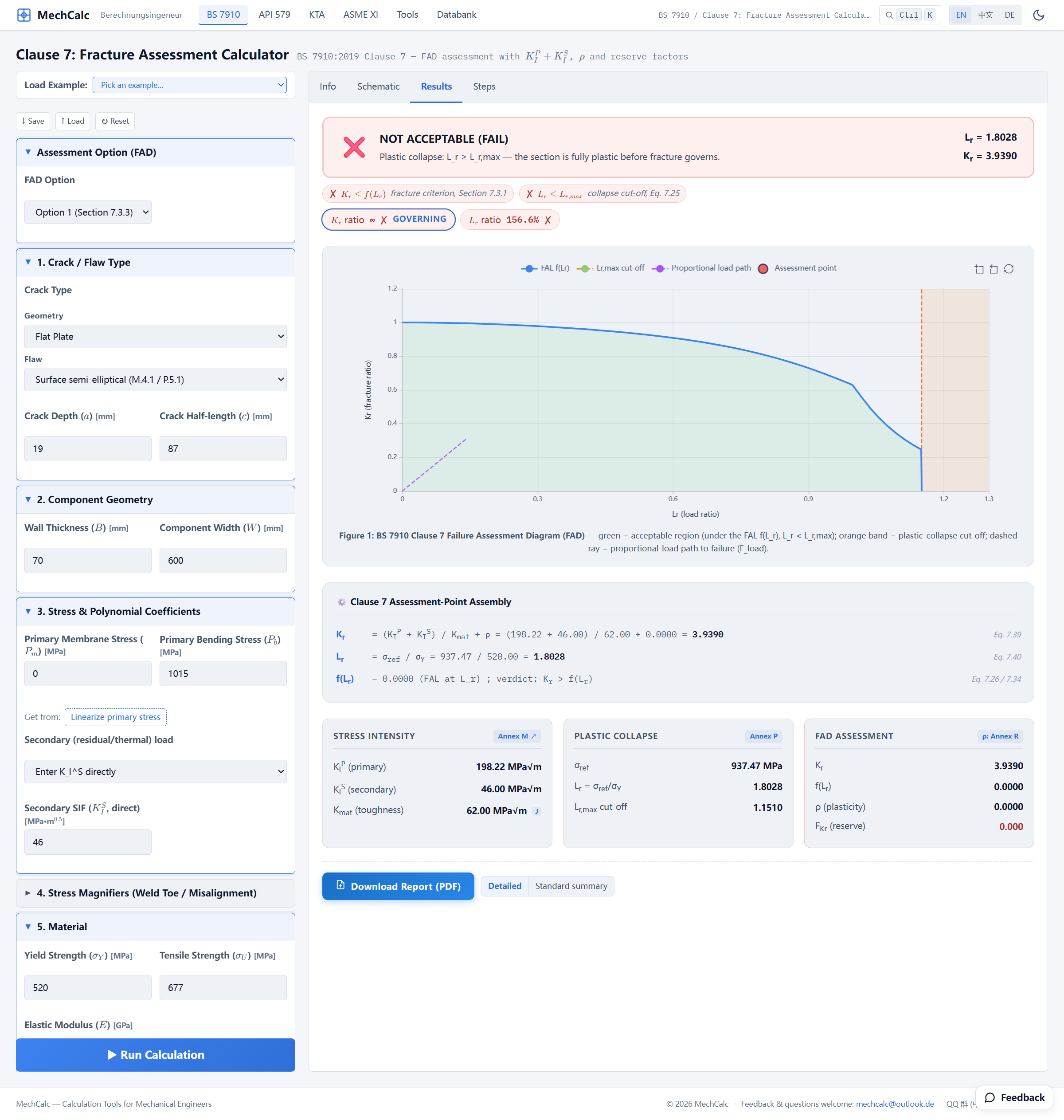 Figure 1: HLAW results. L_r=1.8028 already exceeds the plastic cut-off L_r,max=1.1510, so both the deepest point (K_r=3.9391) and the surface point (K_r=2.2256) lie to the right of the cut-off line. The banner says NOT ACCEPTABLE, with the message “Plastic collapse: L_r ≥ L_r,max — the section is fully plastic before fracture governs.” ρ is 0 at both points and f(L_r)=0.
| Quantity | Deepest point | Surface point | Note |
|---|---|---|---|
| Primary $K_I^P$ [MPa·m$^{0.5}$] | 198.22 | 137.99 | Markedly larger under the high load |
| Secondary $K_I^S$ [MPa·m$^{0.5}$] | 46.00 | 0 | As-welded residual |
| Plasticity interaction $\rho$ | 0 | 0 | $L_r \ge 1.05$, Annex R, Eq. R.2 |
| Ordinate $K_r$ | 3.94 | 2.23 | |
| Reference stress $\sigma_{ref}$ | 937.5 MPa (both points) | Close to yield | |
| Abscissa $L_r$ | 1.80 (both points) | $> L_{r,max}=1.151$ | |
| Verdict at this point | not acceptable (plastic collapse) | not acceptable (plastic collapse) | $L_r \ge L_{r,max}$ |
| Verdict for the flaw | Not acceptable (governed by plastic collapse) |
Reading the result
The abscissa $L_r = 1.80$ is far beyond the plastic cut-off value $L_{r,max}\approx 1.15$. On the FAD, both the deepest point and the surface point fall to the right of the cut-off vertical line — the side controlled by plastic collapse / net-section yielding — so the flawed structure is judged not acceptable, consistent with the test fracture. Here $f(L_r)=0$, so the margin on $K_r$ is $F_{Kr}=0$; the reserve factor on load is $F_{load}=0.063$ (from the deepest point), so the primary load would have to drop to about 6% of its value before the deepest point comes back onto the Failure Assessment Line.
More telling still is that the governing factor has changed. The ordinate $K_r$ reaches 3.94, but this time the main thing driving it up is no longer residual stress: in the large-plasticity regime, secondary stresses such as residual stress are “diluted” by plastic deformation (consistent with the Annex R $\rho$ dropping to zero for $L_r \ge 1.05$ and no longer amplifying secondary stress; BS 7910:2019, Annex R, Eq. R.2). The real weak point is the low fracture toughness — even at −30 ℃, the as-welded weld only reaches $K_{mat}=62$.
In other words: the low-$L_r$ regime (Problems 1 and 2) is a contest over residual stress, whereas the high-$L_r$ regime is a contest over toughness and net-section strength. For one and the same set of specimens, where the operating point sits on the FAD decides who the weak link is — and that is exactly the value of the failure assessment diagram, which unifies brittle fracture and plastic collapse on a single chart.
Comparison with the FITNET result
Setting this high-$L_r$ assessment side by side with the FITNET source (FITNET FFS Procedure MK7 (2006), Vol. II §13.2.5, Table 13.10), item by item. The mechCalc column is the deepest point:
| Quantity | mechCalc (deepest point) | FITNET source | Difference |
|---|---|---|---|
| Primary $K_I^P$ [MPa·m$^{0.5}$] | 198.2 | — | — |
| Secondary $K_I^S$ [MPa·m$^{0.5}$] | 46.0 | 46 | Same source |
| Load ratio $L_r$ | 1.80 | 1.72 | +4.8% |
| Fracture ratio $K_r$ | 3.94 | 3.79 | +3.9% |
Note: the FITNET original (Vol. II §13.2.5, Table 13.10) lists only $K_r$ and $L_r$, not $K_I^P$, so the FITNET column shows “—”.
In the high-$L_r$ regime the gap widens to about 4–5% — but this is not error, it is a difference between two limit-load solutions. For the reference stress, mechCalc uses the closed-form expression from BS 7910 Annex P, whereas FITNET uses the Sattari-Far surface-crack limit-load formula (FITNET Vol. II §13.2.5, Table 13.9 step 8; reference [13.5]); FITNET’s 3D finite-element analysis (ADINA) was used only for the strength-mismatch column ($L_r$ = 2.36), which is not in this table. Two closed-form solutions of the same quantity naturally differ by a few percent at high $L_r$, and here they differ in the same direction, with mechCalc on the slightly more conservative side (its assessment point sits further out, giving a safer verdict). Most importantly, the verdicts agree completely: $L_r$ crosses the cut-off, plastic collapse, not acceptable. The difference therefore sits at the level of the solution used and does not affect the engineering conclusion.
Source: the FITNET project’s Case Studies for Fracture, case “A533B-1 Steel Residual Stress Experiments”; original test report C C France, J K Sharples & C Wignall, AEA Technology Report AEAT-4236 (SINTAP/TASK4/AEAT18, 1998); the HLAW fracture load of 5.10 MN, the roughly 5 mm of ductile tearing before fracture and the assessment inputs are in FITNET FFS Procedure MK7 (2006), Vol. II §13.2.5, Tables 13.9 / 13.10.
The closing problem: same −30 ℃ and high-$L_r$ regime, but with PWHT applied — relaxing the residual stress and raising the toughness by an order of magnitude ($K_{mat}$ jumps from 62 to 321). $K_r$ will collapse, but will the conclusion flip? See Problem 4, HLHT .
🧮 Online calculator: BS 7910 Clause 7 Fracture Assessment Calculator — Try it yourself: P_b=1015, σ_Y=520, σ_U=677, K_mat=62, K_I^S entered directly (46 at the deepest point, 0 at the surface point), and you get L_r=1.80 (past the cut-off) and K_r=3.94 at the deepest point.
Verification manual for this calculator: BS 7910 Fracture Assessment Calculator verification manual