Source: Niemann, G., Winter, H., Höhn, B.-R., & Stahl, K. (2019). Maschinenelemente 1 – Konstruktion und Berechnung von Verbindungen, Lagern, Wellen (5th ed.). Berlin: Springer Vieweg. ISBN 978-3-662-55481-4. Section 10.11, Berechnungsbeispiele (calculation examples), Beispiel 10.2 (Example 10.2), pp. 305–306; some example values: VDI 2230 Part 1:2015-11, steps R3–R9 and R13 (independent hand calculation, inputs from the textbook example).
Calculator: VDI 2230-1 Single-bolt Joint Calculation loads all inputs of this example; press Run Calculation to recompute.
Problem
One M10 necked-down bolt, grade 10.9, thread cut, then heat-treated, joins the big end of a connecting rod to its cap. It passes through holes in both parts and is tightened with a nut (through-bolt joint) using a torque wrench. The clamping length is $l_K = 70$ mm. The book lists two 10 mm segments of 8 mm and 10 mm diameter (the second diameter back-calculated from the printed $\delta_{12}$) and a 40 mm waist of 7.3 mm diameter, 60 mm in all; this example adds the other 10 mm as thread (an assumption). $d_W = 17$ mm, $d_h = 11$ mm, $D_A = 25$ mm. Each bolt carries a pulsating axial load from 0 to $F_A = 15\,000$ N; the residual clamp load must stay at least 500 N (Example 10.2, pp. 305–306).
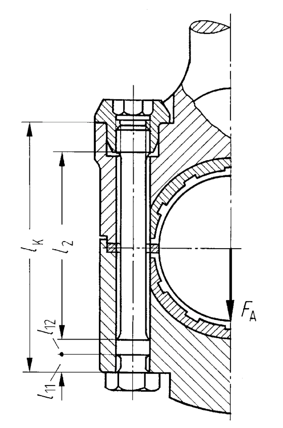 Connecting-rod bolted joint with the clamping length and its sections (Source: Niemann/Winter/Höhn/Stahl, Maschinenelemente 1, 5th ed., Springer Vieweg 2019, Figure 10.17, p. 278)
Inputs
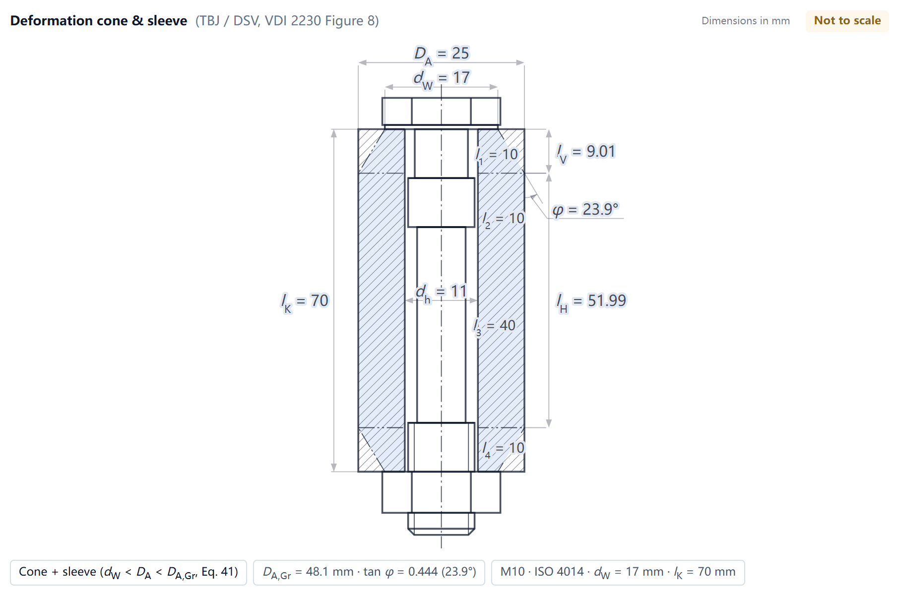 Geometry inputs of this example (drawn by the MechCalc calculator with this example loaded)
| Name | Symbol | Value |
|---|---|---|
| Clamped layers 1, Young’s modulus † | $E_{P}$ | 210000 N/mm² |
| Strength Class | — | 10.9 |
| Yield Strength | $R_{p0{,}2}$ | 940 N/mm² |
| Tensile Strength † | $R_m$ | 1040 N/mm² |
| Elastic Modulus † | $E_S$ | 210000 N/mm² |
| Bolt size | $d$ | M10 |
| Bearing diameter from product data | $d_W$ | 17 mm |
| Clamped layers 1, Thickness | $h$ | 70 mm |
| Equivalent OD at the interface | $D_A$ | 25 mm |
| Through-hole Diameter | $d_h$ | 11 mm |
| Bolt segments 1, Length | $l$ | 10 mm |
| Bolt segments 1, Diameter | $d$ | 8 mm |
| Bolt segments 2, Length | $l$ | 10 mm |
| Bolt segments 3, Length | $l$ | 40 mm |
| Bolt segments 3, Diameter | $d$ | 7.3 mm |
| Bolt segments 4, Length | $l$ | 10 mm |
| Axial Load | $F_A$ | 15000 N |
| Load Introduction Factor | $n$ | 0.5 |
| Required residual clamp load | $F_{KR,req}$ | 500 N |
| Min. Axial Load | $F_{A,min}$ | 0 N |
| Calculation Mode | — | Verification Mode (specified) |
| Joint Type | — | TBJ — Through bolt/DSV |
| Head Type | — | Hexagon head (ISO 4014) |
| Bolt segments 1, Segment type | — | Custom $d$ |
| Bolt segments 2, Segment type | — | Shank ($A_N$) |
| Bolt segments 3, Segment type | — | Custom $d$ |
| Bolt segments 4, Segment type | — | Thread ($A_{d3}$) |
| Thread Friction | $\mu_{G,min}$ | 0.14 |
| Head Friction | $\mu_{K,min}$ | 0.14 |
| Tightening Method | — | Torque controlled (αA from Table A8, default 1.6) |
| Tightening Factor † | $\alpha_A$ | 1.4 |
| Embedding | $f_Z$ | 0.013 mm |
| Fatigue Check | — | Yes |
| Thread Process | — | SV (rolled before heat treatment) |
| Required safety margin against fatigue failure | $S_D$ | 1.5 |
† Not given in the source: The tensile strength $R_m = 1040$ N/mm² is the minimum value for grade 10.9 in Table 10.6 of the same book (p. 270). The tightening factor $\alpha_A = 1.4$ is back-calculated from the book’s $F_{M\max} = \alpha_A\,(F_{KR,\min} + F_{PA} + F_Z) = 22\,712$ N (Eq. 10.72, p. 306): $22\,712/(500 + 14\,100 + 1623) = 1.40$. The elastic moduli $E_S = E_P = 210\,000$ N/mm² are taken from Example 10.1 (p. 304), because the book says that the resilience is calculated as in Example 10.1 (p. 306).
The thread process is set to SV: the book describes the thread as cut and then heat-treated (geschnitten und schlussvergütet, p. 305), and Eq. (10.60) also states that it applies to schlussvergütete Gewinde (p. 284); the German text of VDI 2230 defines SV as schlussvergütete Schraubengewinde (threads heat-treated after forming), and the English column translates this as rolled before heat treatment (VDI 2230 Part 1:2015, Section 5.5.3, Eq. (170)), so the option label and the book mean the same class of thread.
Calculation Steps
Preload (R1–R6)
Step 5 R3a: Bolt axial resilience $\delta_S$ · VDI 2230 Blatt 1:2015, §5.1.1.1, Figure 6, Eq.(18)(19)
$$\delta_S = \delta_{SK} + \sum_i \frac{l_i}{E_S A_i} + \delta_{GM}$$$$\delta_i = \frac{l_i}{E_S A_i}$$Substitution: 4 segment(s): $\delta_{1} = 9.474 \times 10^{-7}$ ($l = 10\,\text{mm}$, custom, $d = 8.000\,\text{mm}$, $A_i = \pi/4\,d_i^2$ (Gl.18))
$\delta_{2} = 6.063 \times 10^{-7}$ ($l = 10\,\text{mm}$, shank, $d = 10.000\,\text{mm}$, $A_N$ (Gl.25))
$\delta_{3} = 4.551 \times 10^{-6}$ ($l = 40\,\text{mm}$, custom, $d = 7.300\,\text{mm}$, $A_i = \pi/4\,d_i^2$ (Gl.18))
$\delta_{4} = 9.106 \times 10^{-7}$ ($l = 10\,\text{mm}$, thread, $d = 8.160\,\text{mm}$, $A_{d3}$ (Gl.23))
$\delta_{SK} = 3.032 \times 10^{-7}$, $\delta_{GM} = 6.978 \times 10^{-7}$ → $\delta_S = 8.0162 \times 10^{-6}\,\text{mm/N}$ (head: hex)
$l_{SK} = 0.5\,d$ (Eq.(30)) is given for the medium series of clearance holes (DIN EN 20273)
check the entered $d_h$ against that series
◆ Compared quantity Bolt resilience $\delta_S$ = $8.01616\times10^{-6}$ mm/N; example value $7.05\times10^{-6}$; error +13.70 % (see “Results Comparison” [1])
Step 6 R3b: Clamped-parts resilience $\delta_P$ · VDI 2230 Blatt 1:2015, §5.1.2.1, Eq.(41)/(46)–(50)
$$\delta_P=\frac{2}{w}\,\delta_P^V+\delta_P^H$$Substitution: branch ③ cone + sleeve ($d_W < D_A < D_{A,Gr}$)
$d_W = 17.00$, $D_A = 25.0$, $d_h = 11.0$, $w = 1$, $\tan\varphi = 0.4441$, $D_{A,Gr} = 48.09$ (mm), $l_V = 9.01$, $l_H = 51.99$ → $\delta_P = 9.9523 \times 10^{-7}\,\text{mm/N}$
◆ Compared quantity Clamped-part resilience $\delta_P$ = $9.95226\times10^{-7}$ mm/N; example value $9.6\times10^{-7}$; error +3.67 % (see “Results Comparison” [2])
Step 8 R3d: Load factor $\Phi_n$ · VDI 2230 Blatt 1:2015, R3/3, Eq.(82)
$$\Phi_n = n \cdot \frac{\delta_P + \delta_{PZu}}{\delta_S + \delta_P}$$Substitution: $\delta_{PZu} = (w-1)\,\delta_M = 0\,\text{mm/N}$
$\Phi_n = 0.5 \cdot (9.9523 \times 10^{-7} + 0) / (8.0162 \times 10^{-6} + 9.9523 \times 10^{-7}) = 0.0552$
◆ Compared quantity Load factor $\Phi$ = 0.0552; example value 0.06; error -8.00 % (see “Results Comparison” [2])
Step 9 R4: Preload change · VDI 2230, R4/1
$$F_Z = \frac{f_Z}{\delta_S + \delta_P}$$Substitution: $F_Z = 0.013 / 9.0114 \times 10^{-6} = 1443\,\text{N}$
◆ Compared quantity Preload loss due to embedding $F_Z$ = 1443 N; example value 1623; error -11.09 % (see “Results Comparison” [2])
Step 10 R5: Minimum assembly preload $F_{M\min}$ · VDI 2230, R5/1
$$F_{M\min} = F_{Kerf} + (1-\Phi)\cdot F_A + F_Z + \Delta F'_{Vth}$$Substitution: $F_{M\min} = 500 + (1-0.0552) \cdot 15000 + 1443 + 0 = 16114\,\text{N}$
◆ Compared quantity Minimum assembly preload $F_{M\min}$ = 16114 N; example value 16114.3; error 0.00 % (see “Results Comparison”)
Step 11 R6: Maximum assembly preload $F_{M\max}$ · VDI 2230, R6/1
$$F_{M\max} = \alpha_A \cdot F_{M\min}$$Substitution: $F_{M\max} = 1.40 \cdot 16114 = 22560\,\text{N}$
◆ Compared quantity Maximum assembly preload $F_{Mmax}$ = 22560 N; example value 22712; error -0.67 % (see “Results Comparison” [2])
Checks (R7–R13)
Step 12 R7: Permissible assembly preload $F_{Mzul}$ · VDI 2230, R7/2
$$F_{Mzul} = A_0 \cdot \frac{\nu \cdot R_{p0{,}2}}{\sqrt{1+3\left[\frac{3}{2}\frac{d_2}{d_0}\left(\frac{P}{\pi d_2}+1.155\mu_{G\min}\right)\right]^2}}$$Substitution: $d_0 = d_i = 7.300\,\text{mm}$ (weakest segment)
$A_0 = 41.9\,\text{mm}^2$
necked-down bolt: $d_0 = d_{i,min}$ per §5.5.1
$\nu = 0.9$, $R_{p0,2} = 940.0\,\text{N/mm}^2$ → $F_{Mzul} = 29153\,\text{N}$
◆ Compared quantity Permissible assembly preload $F_{Mzul}$ = 29153 N; example value 29152.5; error 0.00 % (see “Results Comparison”)
Step 16 R8: Working stress check · VDI 2230, R8/1~R8/5 ✔
$$\sigma_{red,B} = \sqrt{\sigma_{z,\max}^2 + 3(k_\tau \cdot \tau_{\max})^2}$$Substitution: $F_{S\max} = 29981\,\text{N}$, $\sigma_z = 716.3$, $\tau = 369.6$, $\sigma_{red,B} = 784.6$ (N/mm²)
$S_F = 940.0/784.6 = 1.20 \geq 1.0$ → ✅
◆ Compared quantity Safety margin against exceeding the yield point $S_F$ = 1.2; example value 1.55; error -22.58 % (see “Results Comparison” [6])
◆ Compared quantity Maximum bolt load $F_{S\max}$ = 29981 N; example value 29980.8; error 0.00 % (see “Results Comparison”)
◆ Compared quantity Comparative stress in the working state $\sigma_{red,B}$ = 784.6 N/mm²; example value 784.594; error 0.00 % (see “Results Comparison”)
◆ Compared quantity Static strength check: $S_F$ reaches the required value (R8) = Yes; example value Yes; error Match (see “Results Comparison”)
Step 17 R9: Fatigue strength check · VDI 2230, R9/1~R9/5 ✔
$$S_D = \frac{\sigma_{AS}}{\sigma_a} \geq 1.0$$Substitution: $\sigma_a = 7.14$, $\sigma_{AS} = 51.00$ (N/mm²)
$S_D = 7.14 \geq 1.5$ → ✅
required $S_D \ge 1.5$ (set by the user)
◆ Compared quantity Alternating stress $\sigma_a$ = 7.14 N/mm²; example value 8.6; error -16.98 % (see “Results Comparison” [3])
◆ Compared quantity Endurance limit $\sigma_{AS}$ = 51 N/mm²; example value 61.67; error -17.30 % (see “Results Comparison” [4])
◆ Compared quantity Safety margin against fatigue failure $S_D$ = 7.14; example value 7.2; error -0.83 % (see “Results Comparison” [5])
◆ Compared quantity Fatigue check: $S_D$ reaches the required value (R9) = Yes; example value Yes; error Match (see “Results Comparison”)
Step 19 R13: Tightening torque $M_A$ · VDI 2230, R13/1 (Eq.127), Eq.128/129
$$D_{Km} = \frac{d_W + D_{Ki}}{2}$$$$M_A = F_{Mzul}\left[0.16P + 0.58 d_2 \mu_{G\min} + \frac{D_{Km}}{2}\mu_{K\min}\right]$$Substitution: $D_{Km} = (17.00 + 11.00)/2 = 14.00\,\text{mm}$ ($D_{Ki}$ fallback $= d_h$)
$M_A = 29153 \cdot [0.16 \cdot 1.5 + 0.58 \cdot 9.026 \cdot 0.14 + 14.00/2 \cdot 0.14] = 56932\,\text{N}\cdot\text{mm} = 56.9\,\text{N}\cdot\text{m}$
◆ Compared quantity Tightening torque $M_A$ = 56932 N·mm; example value 56932.3; error 0.00 % (see “Results Comparison”)
Results Comparison
| Results | Example | MechCalc | Error (%) |
|---|---|---|---|
| Bolt resilience $\delta_S$ (mm/N) (Step 5) | $7.05\times10^{-6}$ | $8.01616\times10^{-6}$ | +13.70 [1] |
| Clamped-part resilience $\delta_P$ (mm/N) (Step 6) | $9.6\times10^{-7}$ | $9.95226\times10^{-7}$ | +3.67 [2] |
| Load factor $\Phi$ (Step 8) | 0.06 | 0.0552 | -8.00 [2] |
| Preload loss due to embedding $F_Z$ (N) (Step 9) | 1623 | 1443 | -11.09 [2] |
| Maximum assembly preload $F_{Mmax}$ (N) (Step 11) | 22712 | 22560 | -0.67 [2] |
| Alternating stress $\sigma_a$ (N/mm²) (Step 17) | 8.6 | 7.14 | -16.98 [3] |
| Endurance limit $\sigma_{AS}$ (N/mm²) (Step 17) | 61.67 | 51 | -17.30 [4] |
| Safety margin against fatigue failure $S_D$ (Step 17) | 7.2 | 7.14 | -0.83 [5] |
| Safety margin against exceeding the yield point $S_F$ (Step 16) | 1.55 | 1.2 | -22.58 [6] |
| Bolt resilience $\delta_S$ (mm/N) (Step 5) | $8.01616\times10^{-6}$ | $8.01616\times10^{-6}$ | 0.00 |
| Clamped-part resilience $\delta_P$ (mm/N) (Step 6) | $9.95226\times10^{-7}$ | $9.95226\times10^{-7}$ | 0.00 |
| Load factor $\Phi$ (Step 8) | 0.0552205 | 0.0552 | -0.04 |
| Preload loss due to embedding $F_Z$ (N) (Step 9) | 1442.62 | 1443 | +0.03 |
| Minimum assembly preload $F_{M\min}$ (N) (Step 10) | 16114.3 | 16114 | 0.00 |
| Maximum assembly preload $F_{Mmax}$ (N) (Step 11) | 22560 | 22560 | 0.00 |
| Permissible assembly preload $F_{Mzul}$ (N) (Step 12) | 29152.5 | 29153 | 0.00 |
| Maximum bolt load $F_{S\max}$ (N) (Step 16) | 29980.8 | 29981 | 0.00 |
| Comparative stress in the working state $\sigma_{red,B}$ (N/mm²) (Step 16) | 784.594 | 784.6 | 0.00 |
| Safety margin against exceeding the yield point $S_F$ (Step 16) | 1.19807 | 1.2 | +0.16 |
| Tightening torque $M_A$ (N·mm) (Step 19) | 56932.3 | 56932 | 0.00 |
| Alternating stress $\sigma_a$ (N/mm²) (Step 17) | 7.14138 | 7.14 | -0.02 |
| Endurance limit $\sigma_{AS}$ (N/mm²) (Step 17) | 51 | 51 | 0.00 |
| Safety margin against fatigue failure $S_D$ (Step 17) | 7.14148 | 7.14 | -0.02 |
| Static strength check: $S_F$ reaches the required value (R8) (Step 16) | Yes | Yes | Match |
| Fatigue check: $S_D$ reaches the required value (R9) (Step 17) | Yes | Yes | Match |
- [1] The textbook prints $\delta_S = 70.5\times10^{-7}$ mm/N (p. 306, Eq. 10.25), but its terms cover only 60 mm of shank while $l_K = 70$ mm, so the resilience of 10 mm is missing. Taken as thread (an assumption in this example’s input), the missing segment adds $9.11\times10^{-7}$ mm/N, about 12.9 % of the textbook’s chain; the head length $0.4d$ versus the calculator’s $0.5d$ adds another 0.9 % (method difference), and the calculator gets $8.02\times10^{-6}$ mm/N for the full $l_K$. The gap carries over to $\Phi$ and $F_Z$; with the full $l_K$ both the static check and the fatigue check still pass.
- [2] Different clamped-part models (1986 substitute cylinder versus the 2015 cone-and-sleeve model) plus the printed $\delta_S$ missing 10 mm of the bolt; $\Phi$, $F_Z$ and $F_{Mmax}$ follow. The example value of $\Phi$ is converted from the book’s $F_{SA} = 900$ N and $F_A = 15\,000$ N: $\Phi_n = 900/15\,000 = 0.06$ (the printed $\Phi = 0.12$ is not multiplied by $n$).
- [3] The textbook uses the minor-diameter area $A_3$; the calculator uses the stress area $A_S$ as in VDI 2230:2015, and $\Phi_n$ differs (0.0552 versus 0.06).
- [4] The textbook prints $\sigma_A = 0.85\,(150/d + 45) = 61.67$ N/mm² (p. 306), but the same formula (Eq. 10.60, $d$ = nominal diameter) gives 51.0 N/mm² for $d = 10$ mm, and the chart value in Figure 10.28 is 60 N/mm² (p. 285); the printed value is 20.9 % too high. The calculator gives 51.0 from the same formula in VDI 2230:2015, step R9/5-1; with the corrected value the safety margin against fatigue failure is still above $S_{D,min} = 1.5$, so the pass verdict stands.
- [5] The textbook prints $S_D = 7.2$ (p. 306, Eq. 10.76), consistent with its printed $\sigma_A = 61.67$, which is too high (see the note on $\sigma_{AS}$); with $\sigma_A = 51.0$ from its own formula it is 5.93, with the chart value 60 it is 6.98. The calculator’s 7.14 is close to the printed value only because two differences cancel (the high $\sigma_A$ and the different area used for $\sigma_a$); every variant is above $S_{D,min} = 1.5$, so the pass verdict stands.
- [6] The textbook prints $S_F = 1.55$ (p. 306, Eq. 10.75) using $F_{Smax} = 15\,700$ N from the pre-selection Eq. (10.68), although p. 286 says the pre-selection equations are for sizing only, not for the strength check; with $F_{Smax} = F_{Mmax} + F_{SA} = 23\,612$ N from the check Eq. (10.74), the same Eq. (10.75) gives 1.274, so the printed value is 21.7 % too high. The verdict $S_F > S_{F,min} = 1.1$ still holds; the calculator gives 1.20 from VDI 2230:2015, step R8 (a different basis).