🧮 Online calculator: VDI 2230-1 Single-bolt Joint Calculation — The full 14-step calculation chain (R0–R13), with six strength checks.
Checking a Bolted Joint to VDI 2230
[!note] The point in one sentence Is it enough to pick a bolt size from a simplified preselection table, or must the joint go through the full 14-step VDI 2230 check? This article gives a checklist of six conditions, and the limits of what VDI 2230 covers.
In mechanical design the usual practice is to estimate the working load, look up whether a bolt of that size can be pulled apart, and accept it if it is thick enough. In many cases this is good enough, but it rests on one assumption: the joint fails by the bolt being pulled apart.
The problem is that a bolt can fail in more ways than one.
To see why, first look at what a bolted joint actually relies on.
1. Tightening a Bolt Does Two Things
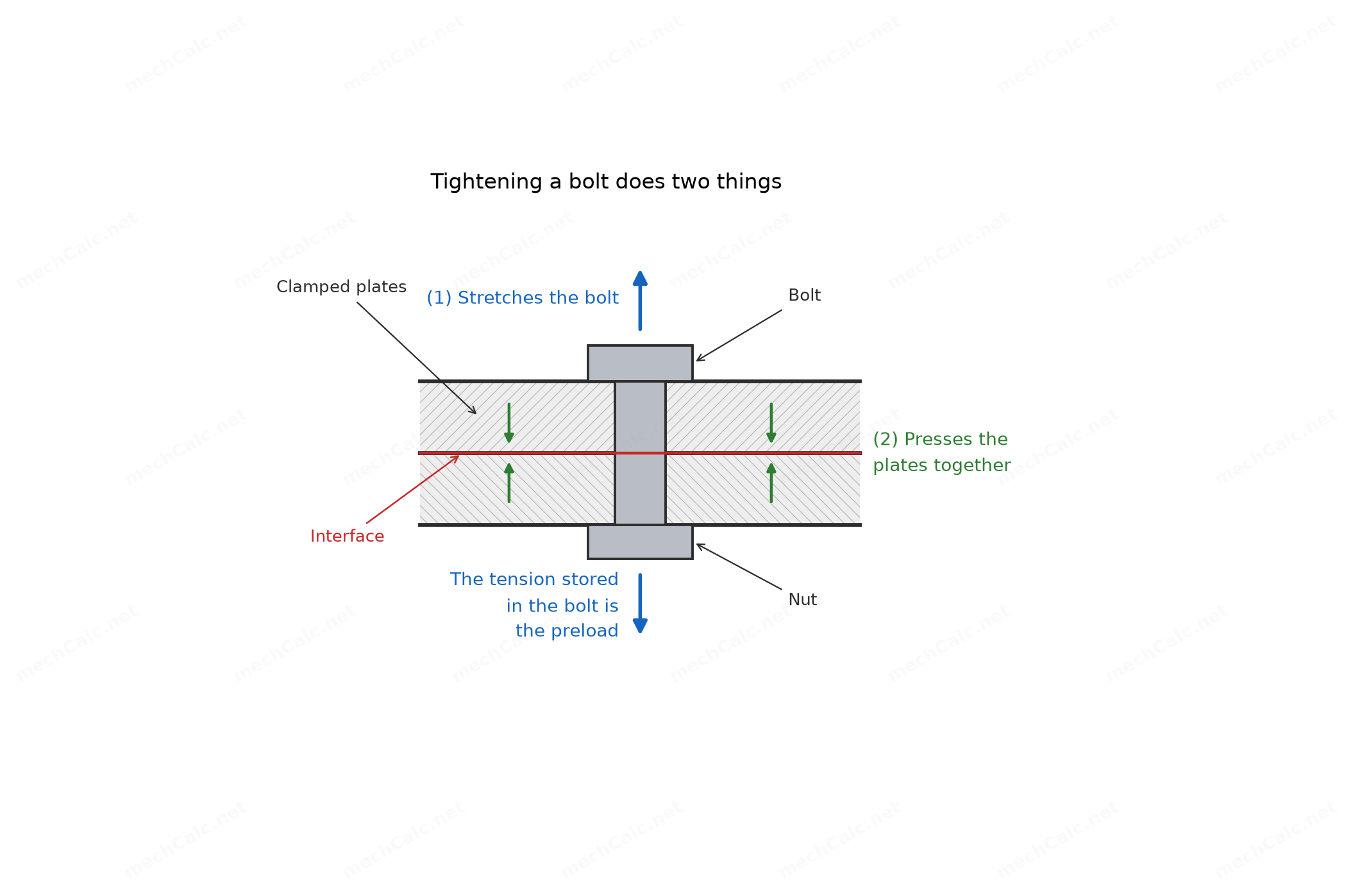 Figure 1: The two things that happen at the same time when a bolt is tightened.
Tightening stretches the bolt a little, and at the same time presses the two plates together.
The stretched bolt tries to shorten again, and this restoring force keeps pressing on the two plates. The tension kept in the bolt is called the preload (Vorspannkraft), and the surface where the two plates touch is called the interface (Trennfuge).
[!important] Everything that follows rests on this sentence The reliability of a bolted joint depends less on how strong the bolt itself is, and more on whether this clamping can be kept for the whole service life.
2. Six Failure Modes, and the Strength Check Covers One
Laid out side by side, the failure modes of bolted joints in practice are roughly these six:
| Failure mode | Main cause | Can a strength check find it? |
|---|---|---|
| Fatigue fracture | After the interface opens, the alternating stress amplitude is multiplied | No |
| Self-loosening | Under alternating transverse load, micro-slip at the interface destroys the friction lock | No |
| Preload relaxation | Embedding after assembly, creep at high temperature | No |
| Thread stripping | Length of engagement too short, or a steel bolt in a soft base material such as aluminium or cast iron | No |
| Crushing of the bearing surface | Surface pressure under the head or nut exceeds the limiting surface pressure of the base material | No |
| Static tensile fracture | The working load directly exceeds the load capacity of the bolt | Yes |
A strength check alone covers only the last row. The first five rows all ask the same question: is the clamping still there?
3. Why the Clamping Cannot Be Kept
Three things can spoil it.
3.1 The tightened preload is not the number you think
An uncertain coefficient of friction, scatter in the coefficient of friction itself, tool errors, and errors in operating and reading the tool all add up. So the actual preload falls in a range, not at one point.
VDI 2230 describes this range with the tightening factor (Anziehfaktor) $\alpha_{\mathrm{A}}$, which is the ratio of the maximum to the minimum assembly preload (VDI 2230:2015, §5.4.3.1, Gl.(130)). Reference values from the standard (VDI 2230:2015, Tabelle A8):
| Tightening method | $\alpha_{\mathrm{A}}$ | Preload scatter |
|---|---|---|
| Yield-controlled, angle-controlled | 1.2 – 1.4 | ±9% – ±17% |
| Torque-controlled, tightening torque determined by test | 1.4 – 1.6 | ±17% – ±23% |
| Torque-controlled, tightening torque from estimated coefficient of friction | 1.6 – 2.5 | ±23% – ±43% |
| Impact wrench, hand tightening | 2.5 – 4 | ±43% – ±60% |
[!tip] How to read this table: the bolt size is set by the two ends of the range With a torque wrench and coefficients of friction estimated from tables, the scatter can reach ±43%; with an impact wrench, ±60%. So two things hold at once: to guarantee the lower limit, the nominal value must be raised; once it is raised, the upper limit may crush the bearing surface or tighten the bolt past its yield point. What sizes the bolt is not the working load itself, but the two ends of this range.
The standard draws this as a figure, which says it more directly than a paragraph can:
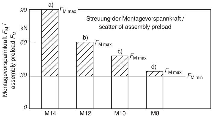 Figure 2: Four tightening methods, one functional requirement. The vertical axis is the assembly preload; the horizontal axis a→d runs from poor to good tightening accuracy. The bottoms of the four bars are level: the minimum preload needed for the function, $F_{\mathrm{M\,min}}$, is the same 30 kN. But the poorer the accuracy and the larger the scatter, the higher the top of the bar, $F_{\mathrm{M\,max}}$, and the bolt has to grow from M8 all the way to M14 to carry that upper limit. Changing the tightening method changes the size by three steps. (Source: VDI 2230 Blatt 1:2015, Bild 27)
Yield-controlled and angle-controlled tightening bring one more benefit: the bolt can be sized for the lower limit, with no extra margin needed for the upper limit (VDI 2230:2015, Tabelle A8). The margin gained by changing the tightening method is often larger than what one bolt size gives.
3.2 When the external load arrives, the bolt does not carry all of it
This is the step that is easiest to get wrong.
When an external load pulls the two plates apart, it is not applied directly to the bolt. Most of the external load is used up in “unloading” the clamping that the interface already has, and only the rest adds load to the bolt.
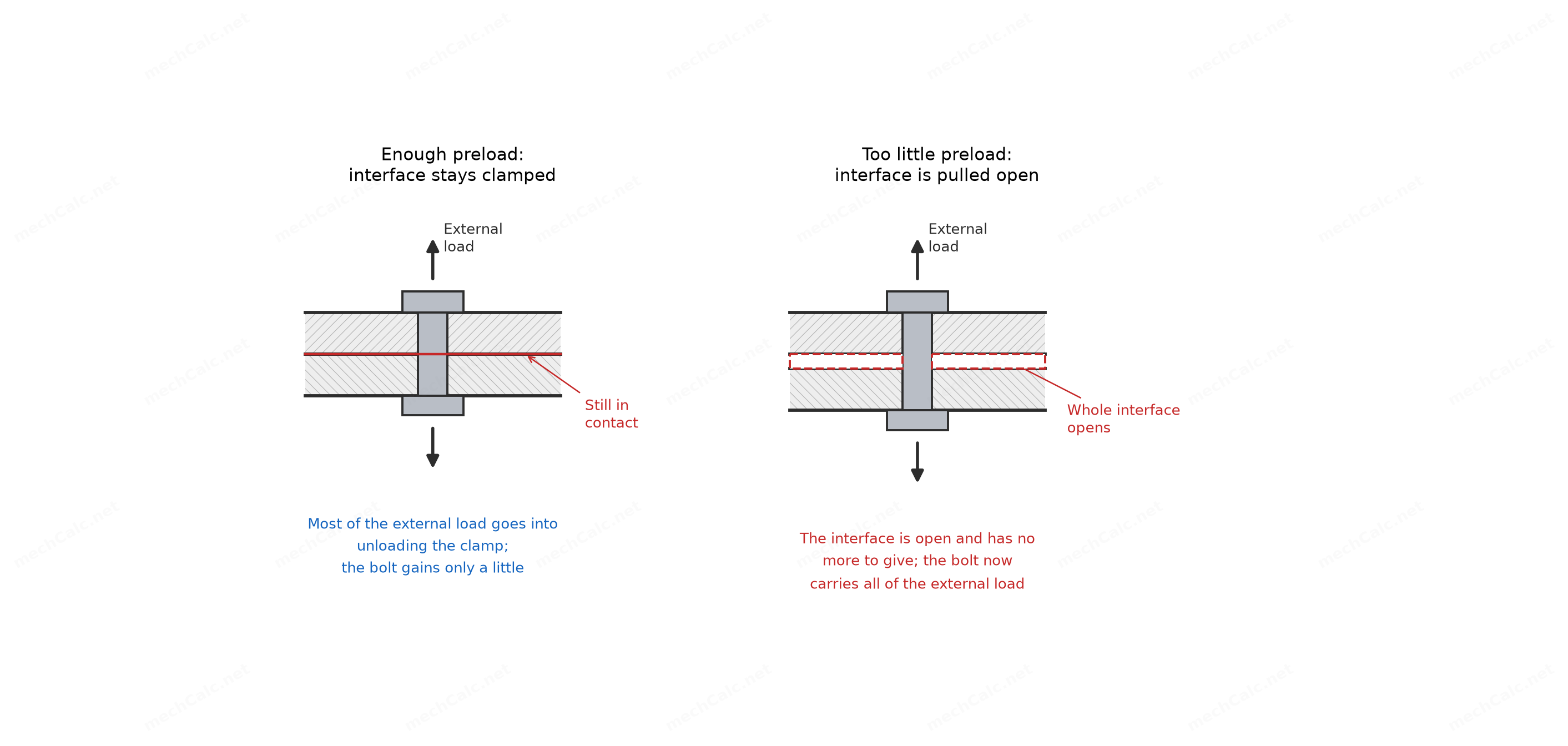 Figure 3: Sufficient preload compared with insufficient preload. On the left the interface is still pressed together, and most of the external load goes into relieving this clamping. On the right the preload is too low and the interface has been pulled open; the external load has nowhere to go, and from then on all of it goes onto the bolt.
How the load divides depends on only two things: which of the bolt and the clamped parts is softer, and where the external load acts (VDI 2230:2015, §3.2.1, Gl.(8)).
[!warning] “The tighter the bolt, the less likely it is to fail in fatigue”: the conclusion is right, but the reason is often given the wrong way round The formula for this division does not contain the preload. It is not that the preload takes over part of the alternating load. A high preload keeps the working state in the situation on the left of Figure 3. Once the preload is too low and the interface is pulled open (Klaffen), it becomes the situation on the right: the external load has nowhere to go, the bolt alone carries all of it, and the alternating stress amplitude rises steeply. This is the cause of “fatigue fracture”, the first row in the failure table.
Two design directions can also be read from this: the stiffer the clamped parts and the closer the load acts to the interface, the smaller the alternating load the bolt takes.
3.3 After assembly, the preload still drops
The roughness peaks on the bearing surfaces, on the loaded thread flanks and on the interfaces are flattened. This plastic flattening is called embedding (Setzen). Note the difference: the part that is flattened during assembly causes no loss; only the part that happens after assembly reduces the preload (VDI 2230:2015, §5.4.2.1).
The standard gives reference values of this size: for roughness $R_z<10\ \mu\mathrm{m}$ under tension-compression loading, about 3 μm in the thread, about 2.5 μm for each head or nut bearing surface, and about 1.5 μm for each inner interface (VDI 2230:2015, Tabelle 5). The more interfaces, the larger the total embedding.
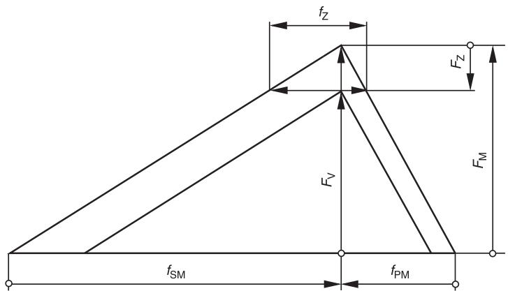 Figure 4: Loss of preload due to embedding. The horizontal axis is deformation and the vertical axis is force. The left branch belongs to the bolt (elongation $f_{\mathrm{SM}}$), the right branch to the clamped parts (compression $f_{\mathrm{PM}}$); the two branches originally meet at $F_{\mathrm{M}}$. After assembly, embedding $f_{\mathrm{Z}}$ occurs, each branch gives way inward, and the intersection slides down the two sloping lines to $F_{\mathrm{V}}$. The drop is the loss $F_{\mathrm{Z}}$. (Source: VDI 2230 Blatt 1:2015, Bild 26)
[!tip] One thing that can be read straight from the figure: the stiffer the joint, the more it suffers from embedding How far the intersection slides down depends on how steep the two sloping lines are. The steeper they are (the stiffer the joint, the smaller the total resilience), the larger the vertical drop $F_{\mathrm{Z}}$ for the same lateral displacement $f_{\mathrm{Z}}$. So short, thick bolts are sensitive to embedding, while long, slender bolts tolerate it better. This is the physical reason for the waisted bolt.
[!warning] Two limits of these reference values (stated in the standard)
- Once the limiting surface pressure is exceeded, the reference values no longer apply. Then, even at room temperature, the clamped parts may creep at the bearing surface, and the amount of embedding grows without control.
- The reference values were measured on solid cylindrical joints. A stack of thin plates has a much larger contact resilience, because the surfaces are not ideally parallel; in this case the preload loss should be measured.
(VDI 2230:2015, §5.4.2.1)
4. The Checklist
For the six conditions below: if any one applies, the joint should be calculated to VDI 2230, not just checked for strength.
- Alternating axial load. Fatigue is then the governing failure mode, and the fatigue stress amplitude depends on how soft the two sides are and where the load acts. A strength check does not give these quantities.
- Transverse load carried by friction. The transverse load is not carried by the bolt shank in shear; it is held by the clamp load at the interface times the coefficient of friction. Too little preload means slip, and slip leads to self-loosening.
- The interface must not open, for example for sealing or to keep positioning accuracy. Preventing opening is a separate requirement on the minimum clamp load and has nothing to do with bolt strength.
- The clamped parts are aluminium, cast iron or another soft material. Crushing of the bearing surface and thread stripping both occur here, and the embedding is also larger.
- Rough tightening method. With an impact wrench or by hand alone, the scatter reaches ±60%, and without the calculation you do not know where the lower limit lies.
- Short clamping length, stiff joint. The embedding loss is magnified; short, thick joints especially need checking.
5. When It Is Not Needed
Conversely, when all of the following apply, simplified preselection tables are usually enough to set the size:
- The load is essentially static, with no marked alternating component.
- Transverse forces are small, or are carried anyway by positive-locking elements such as pins and keys.
- The interface has no sealing or positioning function.
- The clamped parts match the strength of the bolt; there is no soft base material problem.
- The joint is not critical, and the consequences of failure are under control.
[!note] The two are not an either-or choice Simplified preselection gives a starting size quickly; systematic calculation verifies that this size holds for the whole service life. The usual practice in engineering is to preselect first and check afterwards.
6. What the Standard Covers, and What It Does Not
Once you have decided to calculate, you still have to confirm that VDI 2230 Blatt 1 covers your case (VDI 2230:2015, §1).
Covered: steel fastening threads with a 60° flank angle; property classes 8.8 to 12.9, or stainless steel classes 70 and 80; tabulated values given for M4 to M39; working load transmitted by friction and introduced through the clamped parts; load mainly axial, possibly with added bending moment and transverse force. Other materials, lower strengths and larger sizes can be treated by analogy.
Not covered:
- Load distribution in a multi-bolt group. Blatt 1 calculates a single bolt. Finding the most heavily loaded bolt of a group is the job of Blatt 2.
- Determining the external loads. The standard assumes the external loads are known; how to find them is outside its scope.
- Extreme conditions such as corrosion, and impact-type and random loads.
- Material properties other than at room temperature. The tabulated values in the annexes apply only at room temperature.
[!important] A finished calculation is not an exemption from testing The standard states that the calculation result does not do away with the need for testing or finite element verification, which is especially recommended for critical joints (VDI 2230:2015, §1). It provides a set of auditable quantitative criteria, not a certificate that no inspection is needed.
7. How Much Work One Calculation Takes
Fourteen steps, from size estimate to tightening torque: along the way you calculate the bolt resilience, the resilience of the clamped parts, the load introduction factor, the load factor, the minimum clamp load and each preload loss, and then make six strength checks. By hand, with table lookups and substitutions, this takes half a day at least, and a mistake in any lookup means starting again.
This is also the practical reason why the method is used less than it should be. It is not that engineers do not know they should calculate; the cost of one calculation outweighs the benefit.
Once lookups and substitutions are handed to a tool, what remains is the work that belongs to the engineer: judging the loads, choosing the tightening method, deciding the margin.
The calculator on this site covers the full R0–R13 chain (including the chains for transverse load, torque about the bolt axis $M_Y$, sealing, temperature, fatigue and length of engagement). It also covers eccentric clamping and eccentric loading under a tensile working load (VDI 2230:2015, §5.3.2, Table 4, load cases I–III). An external bending moment $M_B$ and a partly opened interface (VDI 2230:2015, Annex D) are not included yet. Such joints still have to be calculated by hand; the formulas for eccentric loads and bending moments are in VDI 2230 (010): Eccentric Loads and Bending Moment Effects .
Data Basis and Accuracy Statement
All formulas, values and quotations in this article come from VDI 2230 Blatt 1:2015-11. Citation format: (VDI 2230:2015, section, formula/table number). The classification and naming of the failure modes is general engineering usage, and the cause of each mode was checked against the text of the standard above.
Figure notes: Figures 1 and 3 were drawn for this article from the mechanical relations described in the standard above. Proportions in the figures are chosen for readability and do not represent true dimensions, and the figures carry the mechCalc.net watermark. Figures 2 and 4 are quoted from the original figures of the standard, with the source stated in the captions; the copyright belongs to the body that issued the standard. They are quoted to explain the provisions of the standard itself, and quoted figures carry no mark of this site.
This article explains the method and contains no worked example. Calculation accuracy and the limits of use are as given in the original standard.
Disclaimer: This article is for engineering teaching reference only. The final responsibility for engineering safety verification rests with the user.
Related Pages
- VDI 2230 (002): Scope and Standard Positioning — the extended version of Section 6 of this article, listing the coverage conditions of the standard one by one and the check of the interface limiting dimension $G$.
- VDI 2230 (003): Spring Model and Force Distribution — the full derivation of how the external load divides in Section 3.2, including the values of the load factor $\Phi$ and the load introduction factor $n$.
- VDI 2230 (006): Preload Design R1–R6 — where Sections 3.1 and 3.3 land in the calculation chain, from the minimum clamp load all the way to the assembly preload.