Source: Verein Deutscher Ingenieure. (2015). VDI 2230 Part 1: Systematic calculation of highly stressed bolted joints – Joints with one cylindrical bolt (German/English ed., November 2015). Düsseldorf: VDI; Berlin: Beuth. Annex B, Example B4, Connecting rod bearing cap bolted joint as an example of eccentric clamping and eccentric loading, pp. 149–158, Figures B4–B6
Calculator: VDI 2230-1 Single-bolt Joint Calculation loads all inputs of this example; press Run Calculation to recompute.
Problem
One M8×53 necked-down bolt of strength grade 12.9 (necked diameter $d_T = 5.82$ mm) joins the bearing cap of a car-engine connecting rod to the rod. It passes through holes in both parts and is tightened with a nut (through-bolt joint), angle-controlled beyond the elastic limit. Inside the clamping length $l_K = 45$ mm the shank has a 22 mm necked section, a 6 mm centering collar, a 15 mm necked section and 2 mm of free thread. The clamped parts are quenched and tempered Cq 45 steel. The interface carries an axial load $F_{A\max} = 5000$ N, a transverse load $F_{Q\max} = 2440$ N and a bending moment of 48 N·m; the interface is not round, so the joint has eccentric clamping and eccentric loading (B4.1 and B4.2, pp. 149–152).
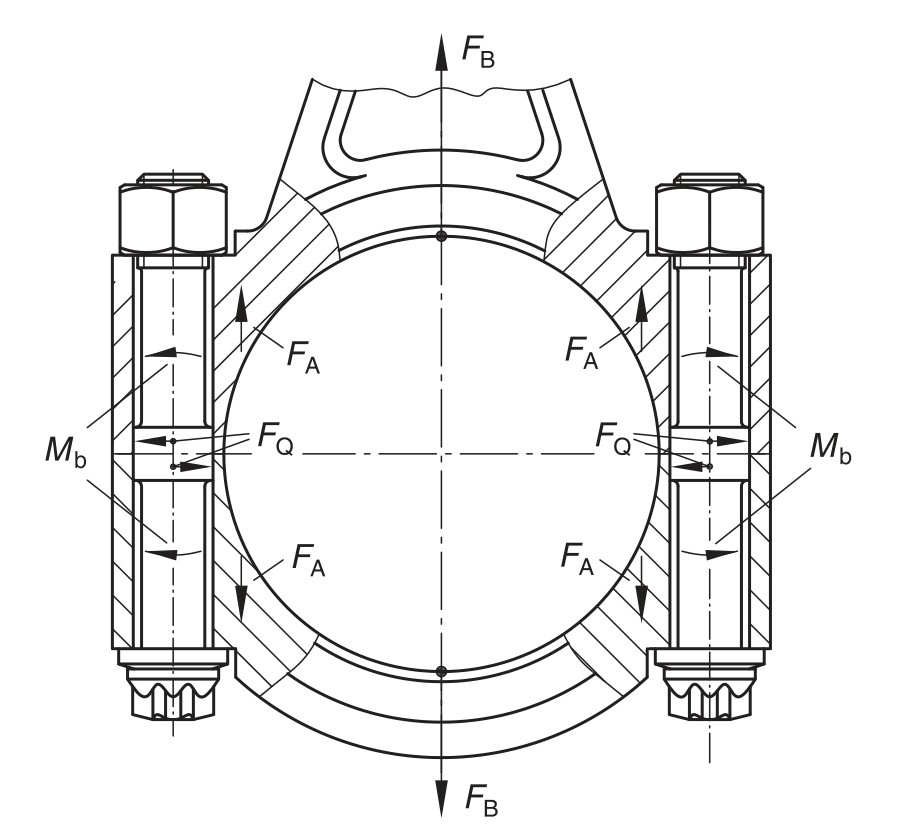 Forces and moments on the bolted joint of a connecting-rod bearing cap (Source: VDI 2230 Part 1:2015, Figure B4, p. 149)
Inputs
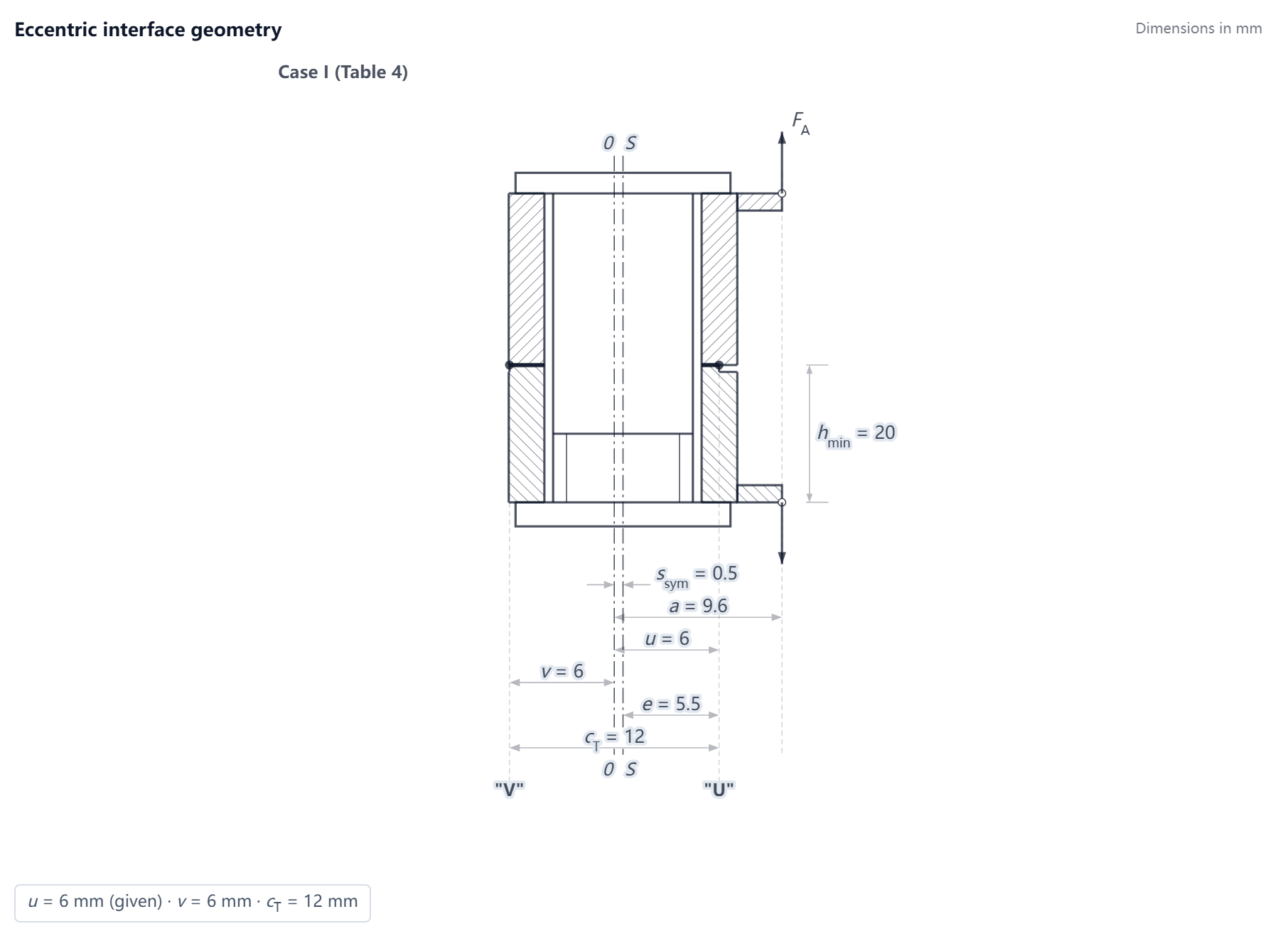 Eccentric interface geometry and load position inputs of this example (drawn by the MechCalc calculator with this example loaded)
| Name | Symbol | Value |
|---|---|---|
| Clamped layers 1, Young’s modulus | $E_{P}$ | 205000 N/mm² |
| Clamped layers 1, Material | — | Cq 45 |
| Clamped layers 1, Limiting surface pressure | $p_{G}$ | 990 N/mm² |
| Clamped layers 2, Young’s modulus | $E_{P}$ | 205000 N/mm² |
| Clamped layers 2, Material | — | Cq 45 |
| Clamped layers 2, Limiting surface pressure | $p_{G}$ | 990 N/mm² |
| Strength Class | — | 12.9 |
| Yield Strength | $R_{p0{,}2}$ | 1100 N/mm² |
| Tensile Strength † | $R_m$ | 1220 N/mm² |
| Elastic Modulus | $E_S$ | 210000 N/mm² |
| Bolt size | $d$ | M8 |
| Bearing diameter from product data | $d_W$ | 12.3 mm |
| Clamped layers 1, Thickness † | $h$ | 25 mm |
| Clamped layers 2, Thickness † | $h$ | 20 mm |
| Equivalent OD at the interface | $D_A$ | 18.6 mm |
| Equivalent OD of the base body (optional) | $D_A'$ | 18.6 mm |
| Through-hole Diameter | $d_h$ | 9 mm |
| Bolt segments 1, Length | $l$ | 22 mm |
| Bolt segments 1, Diameter | $d$ | 5.82 mm |
| Bolt segments 2, Length | $l$ | 6 mm |
| Bolt segments 2, Diameter | $d$ | 9 mm |
| Bolt segments 3, Length | $l$ | 15 mm |
| Bolt segments 3, Diameter | $d$ | 5.82 mm |
| Bolt segments 4, Length | $l$ | 2 mm |
| Head-side bearing-face inner diameter (optional) | $D_{Ki}$ | 9 mm |
| Nut bearing-face outer diameter (optional) | $d_{WMu}$ | 11.6 mm |
| Nut-side bearing-face inner diameter (optional) | $D_{Ki,Mu}$ | 9 mm |
| Distance bearing face → load point (optional) | $a_k$ | 0 mm |
| Length basic solid → load point (optional) | $l_A$ | 2.95 mm |
| Clamping eccentricity | $s_{sym}$ | 0.5 mm |
| Loading eccentricity | $a$ | 9.6 mm |
| Opening-side edge distance | $e$ | 5.5 mm |
| Opening-point distance | $u$ | 6 mm |
| Interface dimension | $c_T$ | 12 mm |
| Deformation sleeve width | $b$ | 25 mm |
| Opening-check contact area | $A_D$ | 208.4 mm² |
| Interface moment of gyration | $I_{BT}$ | 3600 mm⁴ |
| Thinner clamped plate | $h_{min}$ | 20 mm |
| Axial Load | $F_A$ | 5000 N |
| Transverse Load | $F_Q$ | 2440 N |
| Load Introduction Factor | $n$ | 0.58 |
| Calculation Mode | — | Verification Mode (specified) |
| Joint Type | — | TBJ — Through bolt/DSV |
| Head Type | — | Special head (enter the bearing diameter) |
| Bolt segments 1, Segment type | — | Custom $d$ |
| Bolt segments 2, Segment type | — | Custom $d$ |
| Bolt segments 3, Segment type | — | Custom $d$ |
| Bolt segments 4, Segment type | — | Thread ($A_{d3}$) |
| Joint type for load introduction (optional) | — | SV 1 |
| Friction class (Table A5) | — | B |
| Thread Friction | $\mu_{G,min}$ | 0.08 |
| Interface Friction | $\mu_{T,min}$ | 0.15 |
| Number of force-transmitting inner interfaces | $q_F$ | 1 |
| Tightening Method | — | Angle controlled (αA = 1.0) |
| Tightening Factor | $\alpha_A$ | 1 |
| Embedding amount | — | From Table 5 (add up) |
| Surface roughness | $R_z$ | 10 ≤ Rz < 40 μm |
| Load direction (Table 5) | — | Tension / compression |
| Number of inner interfaces | — | 1 |
| Hardening coefficient | $k_V$ | 1.15 |
| Max thread friction (optional) | $\mu_{G,max}$ | 0.14 |
| Thread Process | — | SV (rolled before heat treatment) |
| Eccentric clamping / loading | — | Yes |
† Not given in the source: The clamped layers are 25 mm thick on the head side and 20 mm on the nut side. The standard prints only $l_K = 45$ mm and the thinner plate $h_{min} = 20$ mm (Figure B5, p. 150) and does not say on which side the thinner plate is; the orientation of Figures B4 and B5 puts it on the head side, but the centering collar in Figure B6 lies 22 mm to 28 mm below the head (p. 151) and R4 leaves the transverse load out of the embedding because of that collar (p. 154), so the interface must lie within the collar, which needs 25 mm on the head side, and this example takes that reading; both layers have the same material, and swapping the two thicknesses changes no checked value and no check result. The tensile strength of the bolt $R_m = 1220$ N/mm² is the minimum value for strength class 12.9 (DIN EN ISO 898-1:2013-05, Section 7, Table 3).
Calculation Steps
Preload (R1–R6)
Step 6 R2: Required minimum clamp load $F_{Kerf}$ · VDI 2230 Blatt 1:2015, R2/1~R2/4 (Eq.108/109/107/110/111)
$$F_{KA}=F_{A\max}\frac{A_D(a\,u-s_{sym}u)}{I_{BT}+s_{sym}u A_D}$$$$F_{Kerf}\geq\max(F_{KQ};\,\max(F_{KP},F_{KR,req})+F_{KA})$$Substitution: $F_{KQ} = 2440/(1 \cdot 0.15) = 16267\,\text{N}$ (friction)
$F_{KP} = 0\,\text{N}$ (sealing)
$F_{KR,req} = 0\,\text{N}$ (specified)
$F_{Kerf} = 16267\,\text{N}$
$F_{A\max} = 5000$, $a = 9.600$, $u = 6.000$, $s_{sym} = 0.500$, $A_D = 208$, $I_{BT} = 3600$ (input) → $F_{KA} = 13465\,\text{N}$ (opening limit, VDI 2230 Part 1:2015, §5.3.2, Eq. (107))
$A_D$ here is the contact area of the opening model, not the sealing area of $F_{KP}$
◆ Compared quantity Clamp load required to transmit the transverse load $F_{KQ}$ = 16266.7 N; example value 16267; error 0.00 % (see “Results Comparison”)
◆ Compared quantity Required clamp load $F_{Kerf}$ = 16266.7 N; example value 16267; error 0.00 % (see “Results Comparison”)
◆ Compared quantity Anti-opening clamp load $F_{KA}$ = 13465.2 N; example value 13465; error 0.00 % (see “Results Comparison”)
Step 7 R3a: Bolt axial resilience $\delta_S$ · VDI 2230 Blatt 1:2015, §5.1.1.1, Figure 6, Eq.(18)(19)
$$\delta_S = \delta_{SK} + \sum_i \frac{l_i}{E_S A_i} + \delta_{GM}$$$$\delta_i = \frac{l_i}{E_S A_i}$$Substitution: 4 segment(s): $\delta_{1} = 3.938 \times 10^{-6}$ ($l = 22\,\text{mm}$, custom, $d = 5.820\,\text{mm}$, $A_i = \pi/4\,d_i^2$ (Gl.18))
$\delta_{2} = 4.491 \times 10^{-7}$ ($l = 6\,\text{mm}$, custom, $d = 9.000\,\text{mm}$, $A_i = \pi/4\,d_i^2$ (Gl.18))
$\delta_{3} = 2.685 \times 10^{-6}$ ($l = 15\,\text{mm}$, custom, $d = 5.820\,\text{mm}$, $A_i = \pi/4\,d_i^2$ (Gl.18))
$\delta_{4} = 2.900 \times 10^{-7}$ ($l = 2\,\text{mm}$, thread, $d = 6.466\,\text{mm}$, $A_{d3}$ (Gl.23))
$\delta_{SK} = 3.789 \times 10^{-7}$, $\delta_{GM} = 8.832 \times 10^{-7}$ → $\delta_S = 8.6242 \times 10^{-6}\,\text{mm/N}$ (head: custom)
$l_{SK} = 0.5\,d$ (Eq.(30)) is given for the medium series of clearance holes (DIN EN 20273)
check the entered $d_h$ against that series
◆ Compared quantity Bolt resilience $\delta_S$ = $8.62419\times10^{-6}$ mm/N; example value $8.62\times10^{-6}$; error +0.05 % (see “Results Comparison”)
Step 9 R3b: Clamped-parts resilience $\delta_P$ · VDI 2230 Blatt 1:2015, §5.1.2.1, Eq.(41)/(46)–(50)
$$\delta_P=\frac{2}{w}\,\delta_P^V+\delta_P^H$$Substitution: branch ③ cone + sleeve ($d_W < D_A < D_{A,Gr}$)
$d_W = 12.30$, $D_A = 18.6$, $d_h = 9.0$, $w = 1$, $D_A' = 18.6$, $\tan\varphi = 0.4446$, $D_{A,Gr} = 32.31$ (mm), $l_V = 7.09$, $l_H = 30.83$ → $\delta_P = 1.3503 \times 10^{-6}\,\text{mm/N}$
◆ Compared quantity Clamped-part resilience $\delta_P$ = $1.35034\times10^{-6}$ mm/N; example value $1.351\times10^{-6}$; error -0.05 % (see “Results Comparison”)
Step 10 R3b-e: Eccentric clamping — $I_{Bers}$, $\delta_P^*$, $\delta_P^{**}$ · VDI 2230 Blatt 1:2015, §5.1.2.2–§5.1.2.3, Eq.(59)–(62), (64), (67), (71)
$$I_{Bers}=\frac{l_K}{\frac{2}{w}\frac{l_V}{I^{Ve}_{Bers}}+\frac{l_H}{I^H_{Bers}}}$$$$\delta_P^{*}=\delta_P+\frac{s_{sym}^2 l_K}{E_P I_{Bers}}$$$$\delta_P^{**}=\delta_P+\frac{a\,s_{sym} l_K}{E_P I_{Bers}}$$Substitution: $I^V_{Bers} = 2424$, $I^{Ve}_{Bers} = 2492\,\text{mm}^4$
$I^H_{Bers} = 3600\,\text{mm}^4$ ($b = 25$)
$I_{Bers} = 3158$, $\bar I_{Bers} = 2836\,\text{mm}^4$
$\delta_P^{*} = 1.3677 \times 10^{-6}$, $\delta_P^{**} = 1.6840 \times 10^{-6}\,\text{mm/N}$
◆ Compared quantity Substitutional moment of gyration of a deformation cone $I_{Bers}^{V}$ = 2424.5 mm⁴; example value 2424.5; error 0.00 % (see “Results Comparison”)
◆ Compared quantity Moment of gyration of the deformation cone including the eccentricity $s_{sym}$, $I_{Bers}^{Ve}$ = 2492.4 mm⁴; example value 2492.4; error 0.00 % (see “Results Comparison”)
◆ Compared quantity Substitutional moment of gyration of a deformation sleeve $I_{Bers}^{H}$ = 3600 mm⁴; example value 3600; error 0.00 % (see “Results Comparison”)
◆ Compared quantity Substitutional moment of gyration of the deformation body $I_{Bers}$ = 3158.1 mm⁴; example value 3157.8; error +0.01 % (see “Results Comparison”)
◆ Compared quantity Clamped-part resilience under eccentric clamping $\delta_P^{*}$ = $1.36771\times10^{-6}$ mm/N; example value $1.368\times10^{-6}$; error -0.02 % (see “Results Comparison”)
◆ Compared quantity Clamped-part resilience under eccentric clamping and eccentric loading $\delta_P^{**}$ = $1.68398\times10^{-6}$ mm/N; example value $1.685\times10^{-6}$; error -0.06 % (see “Results Comparison”)
Step 12 R3d: Load factor $\Phi^*_{en}$ · VDI 2230 Blatt 1:2015, R3/4, Eq.(91), (92)
$$\Phi^*_{en} = n \cdot \frac{\delta_P^{**} + \delta_{PZu}}{\delta_S + \delta_P^{*}}$$Substitution: $\delta_{PZu} = (w-1)\,\delta_M = 0\,\text{mm/N}$
$\Phi^*_{en} = 0.58 \cdot (1.6840 \times 10^{-6} + 0) / (8.6242 \times 10^{-6} + 1.3677 \times 10^{-6}) = 0.097750$
◆ Compared quantity Load factor $\Phi$ = 0.0977; example value 0.098; error -0.31 % (see “Results Comparison”)
Step 13 R4: Preload change · VDI 2230-1:2015, §5.4.2.1, Table 5
$$f_Z = \frac{f_{Z,thread} + n_{bearing} f_{Z,bearing} + n_{inner} f_{Z,inner}}{1000}$$$$F_Z = \frac{f_Z}{\delta_S + \delta_P}$$Substitution: Table 5, $10 \leq R_z < 40\,\mu\text{m}$, tension/compression: thread 3 μm
bearing areas 2 × 3 μm
inner interfaces 1 × 2 μm
total 11 μm = 0.011 mm
$F_Z = 0.011 / 9.9745 \times 10^{-6} = 1103\,\text{N}$
Table 5 applies to compact steel parts without coatings only
aluminium parts embed more (e.g. 10 μm instead of 5 μm at the thread of a tapped thread joint) (VDI 2230-1 §5.4.2.1)
above the limit surface pressure $p_G$ of Table A9 the Table 5 values are no longer valid
for a stack of thin plates measure $F_Z$ by test (VDI 2230-1 §5.4.2.1)
Table 5 has separate shear values
Annex B takes shear for Examples B2 and B3 and tension for B4 where a centering collar carries the transverse load
◆ Compared quantity Amount of embedding $f_Z$ (thread) = 3 μm; example value 3; error 0.00 % (see “Results Comparison”)
◆ Compared quantity Amount of embedding $f_Z$ (each head or nut bearing area) = 3 μm; example value 3; error 0.00 % (see “Results Comparison”)
◆ Compared quantity Amount of embedding $f_Z$ (each inner interface) = 2 μm; example value 2; error 0.00 % (see “Results Comparison”)
◆ Compared quantity Amount of embedding $f_Z$ = 11 μm; example value 11; error 0.00 % (see “Results Comparison”)
◆ Compared quantity Preload loss due to embedding $F_Z$ = 1103 N; example value 1103; error 0.00 % (see “Results Comparison”)
Step 14 R5: Minimum assembly preload $F_{M\min}$ · VDI 2230, R5/1
$$F_{M\min} = F_{Kerf} + (1-\Phi^*_{en})\cdot F_A + F_Z + \Delta F'_{Vth}$$Substitution: $F_{M\min} = 16267 + (1-0.0977) \cdot 5000 + 1103 + 0 = 21881\,\text{N}$
◆ Compared quantity Minimum assembly preload $F_{M\min}$ = 21881 N; example value 21880; error 0.00 % (see “Results Comparison”)
Step 15 R6: Maximum assembly preload $F_{M\max}$ · VDI 2230, R6/1
$$F_{M\max} = \alpha_A \cdot F_{M\min}$$Substitution: $F_{M\max} = 1.00 \cdot 21881 = 21881\,\text{N}$
◆ Compared quantity Maximum assembly preload $F_{Mmax}$ = 21881 N; example value 21880; error 0.00 % (see “Results Comparison”)
Checks (R7–R13)
Step 16 R7: Permissible assembly preload $F_{Mzul}$ · VDI 2230-1:2015, §5.5.1; Annex B, Example B4, R7
$$F_{Mzul} = \frac{F_{MTab}}{\nu_{Tab}}$$Substitution: $d_0 = d_i = 5.820\,\text{mm}$ (weakest segment)
$A_0 = 26.6\,\text{mm}^2$
necked-down bolt: $d_0 = d_{i,min}$ per §5.5.1
tightening beyond the elastic limit (yield- or angle-controlled): $F_{Mzul} = F_{MTab}/\nu_{Tab} = 23798/0.9$ ($\nu_{Tab} = 0.9$; the input $\nu$ is not used), $R_{p0,2} = 1100.0\,\text{N/mm}^2$ → $F_{Mzul} = 26442\,\text{N}$
◆ Compared quantity Relevant section area $A_0$ = 26.603 mm²; example value 26.6; error +0.01 % (see “Results Comparison”)
◆ Compared quantity Permissible assembly preload $F_{Mzul}$ = 26442 N; example value 26444; error -0.01 % (see “Results Comparison” [1])
Step 17 R7b: Permissible assembly preload upper bound · VDI 2230 Blatt 1:2015, §5.5.1, Eq.(147) ✔
$$F_{Mmax}\ \leq\ F_{Mzul}\ \leq\ 1.4\,F_{MTab}$$Substitution: $F_{MTab} = 23798\,\text{N}$ — the Table A1–A4 value: 90 % of $R_{p0,2\min}$, Eq. (142)/(143) evaluated with $\nu = 1$ (VDI 2230 Part 1:2015, §5.5.1)
upper bound $1.4\,F_{MTab} = 33317\,\text{N}$, $F_{Mzul} = 26442\,\text{N}$
$F_{Mzul}/F_{MTab} = 1/0.9 = 1.111$
◆ Compared quantity Table assembly preload $F_{MTab}$ = 23798 N; example value 23800; error -0.01 % (see “Results Comparison” [1])
Step 21 R8b: Post-yield preload $F_{V1}$ and minimum clamp load · VDI 2230 Blatt 1:2015, §5.5.2.4, Eq.(164)(166)(167) ✔
$$F_{V1}=A_0\sqrt{(R_{p0{,}2min}k_V)^2-3\left(k_\tau\frac{M_G}{W_{Ppl}}\right)^2}-F_{SAmax}+\Delta F_{Vth}^{*}-F_Z$$Substitution: branch (b) tightened beyond yield (§5.5.2.3)
$\mu_{G\max} = 0.14$
$W = 51.6\,\text{mm}^3$, $k_V = 1.15$, $\tau_S = 181.5\,\text{N/mm}^2$
$F_{V1} = 31006\,\text{N}$ (thermal term by Eq. (151), VDI 2230 Part 1:2015, §5.5.2.1: 0 N)
$F_{M0,2\min} = F_{MTab}(\mu_{G\max})/\nu_{Tab} = 21612/0.9 = 24013\,\text{N}$, $M_G = 18733\,\text{N}\cdot\text{mm}$
$F_{V1\min} = 22911\,\text{N}$ (thermal term by Eq. (167), the opposite sign rule, VDI 2230 Part 1:2015, §5.5.2.4: 0 N)
$F_{PA\max} = 4511\,\text{N}$
$F_{KR1\min} = 18399\,\text{N}$ vs $F_{Kerf} = 16267\,\text{N}$
bending term $M_{Sbmax}$ of Eq.(157)/(161) not included (eccentric, same simplification as R8)
◆ Compared quantity Preload after the first loading/unloading cycle when the yield point has been exceeded $F_{V1}$ = 31006 N; example value 31011; error -0.02 % (see “Results Comparison” [1])
◆ Compared quantity Minimum residual clamp load after yielding $F_{KR1min}$ = 18399 N; example value 18276; error +0.67 % (see “Results Comparison” [1])
◆ Compared quantity Residual clamp load after yielding: $F_{KR1min} \geq F_{Kerf}$ (Eq. 164) = Yes; example value Yes; error Match (see “Results Comparison”)
Step 22 R9: Fatigue stress $\sigma_{ab}$ & $S_D$ (eccentric) · VDI 2230 Blatt 1:2015, R9/2, Eq.(169), (188), (64), R9/4 ✔
$$\sigma_{SAb}=\left[1+\left(\frac{1}{\Phi^*_{en}}-\frac{s_{sym}}{a}\right)\frac{l_K}{l_{ers}}\frac{E_S}{E_P}\frac{\pi a d_S^3}{8\bar I_{Bers}}\right]\frac{\Phi^*_{en}F_A}{A_S}$$$$\ \sigma_{ab}=\frac{\sigma_{SAbo}-\sigma_{SAbu}}{2}$$$$\ S_D=\frac{\sigma_{AS}}{\sigma_{ab}}\geq1.0$$Substitution: $1/\Phi^*_{en} - s_{sym}/a = 1/0.097750 - (0.500)/9.600$
$l_K/l_{ers} = 45.000/67.042$, $E_S/E_P = 210000/205000$, $\pi a d_S^3/(8\bar I_{Bers}) = \pi\cdot9.600\cdot6.827^3/(8\cdot2836)$ → bracket $= 3.9601$
$\sigma_{SAb}/F_A = \text{bracket}\cdot\Phi^*_{en}/A_S = 1.0577e-02\,\text{mm}^{-2}$
$\sigma_{SAbo} = 52.883$, $\sigma_{SAbu} = 0.000$, $\sigma_{ab} = 26.441$ (N/mm²)
$\sigma_{AS} = 54.19$ (N/mm²)
$S_D = 2.05 \geq 1.2$ → ✅
required $S_D \ge 1.2$ (recommended value 1.2 per [4] in R9/4; the safety margin is set by the user)
if the connection opens locally, $F_{SAKl}/F_A$ of Annex D is recommended in place of $\Phi^*_{en}$ (VDI 2230 Part 1:2015, §5.5.3, Eq. (188); Annex D) — this calculator guarantees no opening via R3e, Annex D is not included
◆ Compared quantity Endurance limit $\sigma_{AS}$ = 54.19 N/mm²; example value 54; error +0.35 % (see “Results Comparison”)
◆ Compared quantity Fatigue check: $S_D$ reaches the required value (R9) = Yes; example value Yes; error Match (see “Results Comparison” [2])
Step 23 R10: Surface pressure check (assembly and working state) · VDI 2230, R10/3, Eq.(192), R10/2 (Eq.191), R10/4; Eq.129/193/194; §5.5.4; Annex B, Example B4, R10 ✔
$$A_{p\min} = \tfrac{\pi}{4}(d_{Wa}^2 - D_{Ki}^2)$$$$p_{\max} = 1.4\,\frac{F_{MTab}}{A_{p\min}}$$$$p_{B\max} = \frac{F_{V\max} + F_{SA\max} - \Delta F_{Vth}}{A_{p\min}} \le p_G$$Substitution: Head side: $D_{Ki} = 9.00\,\text{mm}$, $d_{Wa} = 12.30\,\text{mm}$, $A_{p\min} = \tfrac{\pi}{4}(12.30^2 - 9.00^2) = 55.2\,\text{mm}^2$
$p_{\max} = 1.4\,F_{MTab}/A_{p\min} = 1.4 \cdot 23798/55.2 = 603.5\,\text{N/mm}^2$ (R10/3, Eq.(192))
$p_{B\max} = (26442 + 489 - 0)/55.2 = 487.8\,\text{N/mm}^2$
$F_{SA\max} = \Phi^*_{en} F_{A\max}$ ($\Phi^*_{en} = 0.097750$, R10/2)
head side $p_G = 990\,\text{N/mm}^2$ (input): $S_p = 1.64$, $S_{pB} = 2.03$
Nut side: $d_{WMu} = 11.6\,\text{mm}$ (entered), $D_{Ki,Mu} = 9.00\,\text{mm}$, $d_{Wa,Mu} = 11.60\,\text{mm}$, $A_{pMu,\min} = \tfrac{\pi}{4}(11.60^2 - 9.00^2) = 42.1\,\text{mm}^2$
$p_{Mu\max} = 792.0\,\text{N/mm}^2$
$p_{B\max,Mu} = 640.2\,\text{N/mm}^2$
nut side $p_G = 990\,\text{N/mm}^2$ (input): $S_p = 1.25$, $S_{pB} = 1.55$
critical side: nut
◆ Compared quantity Minimum bearing area $A_{p\min}$ (head side) = 55.2 mm²; example value 55.2; error 0.00 % (see “Results Comparison”)
◆ Compared quantity Minimum bearing area $A_{p\min}$ (nut side) = 42.1 mm²; example value 42.1; error 0.00 % (see “Results Comparison”)
◆ Compared quantity Surface pressure in the assembly state $p_{M\max}$ (head side) = 603.5 N/mm²; example value 603; error +0.08 % (see “Results Comparison” [1])
◆ Compared quantity Surface pressure in the assembly state $p_{M\max}$ (nut side) = 792 N/mm²; example value 791; error +0.13 % (see “Results Comparison” [1])
◆ Compared quantity Safety margin against surface pressure $S_P$ (assembly state, head side) = 1.64; example value 1.64; error 0.00 % (see “Results Comparison” [1])
◆ Compared quantity Safety margin against surface pressure $S_P$ (assembly state, nut side) = 1.25; example value 1.25; error 0.00 % (see “Results Comparison” [1])
Step 24 R12: Safety margin against slipping $S_G$ · VDI 2230-1:2015, R12/4; §5.5.2.4 Eq.(164); Annex B, Example B4, R12 ✘
$$F_{KQ,erf} = \frac{F_{Q\max}}{q_F\,\mu_{T\min}} + \frac{M_{Y\max}}{q_M\,r_a\,\mu_{T\min}}$$$$S_G = \frac{F_{KR\min}}{F_{KQ,erf}} > 1.0$$Substitution: $F_{KQ,erf} = 2440/(1 \cdot 0.15) = 16267\,\text{N}$
$F_{KR\min} = 18399\,\text{N}$ ($F_{KRmin}=F_{KR1min}$ (R8b)) → $S_G = 1.13$ ❌
required $S_G \ge 1.2$ (static loading, normal value of R12/4; the safety margin is set by the user)
◆ Compared quantity Safety margin against slipping $S_G$ = 1.13; example value 1.12; error +0.89 % (see “Results Comparison” [1])
◆ Compared quantity Slip check: $S_G$ reaches the required value (R12) = No; example value No; error Match (see “Results Comparison”)
Results Comparison
| Results | Example | MechCalc | Error (%) |
|---|---|---|---|
| Clamp load required to transmit the transverse load $F_{KQ}$ (N) (Step 6) | 16267 | 16266.7 | 0.00 |
| Required clamp load $F_{Kerf}$ (N) (Step 6) | 16267 | 16266.7 | 0.00 |
| Anti-opening clamp load $F_{KA}$ (N) (Step 6) | 13465 | 13465.2 | 0.00 |
| Bolt resilience $\delta_S$ (mm/N) (Step 7) | $8.62\times10^{-6}$ | $8.62419\times10^{-6}$ | +0.05 |
| Clamped-part resilience $\delta_P$ (mm/N) (Step 9) | $1.351\times10^{-6}$ | $1.35034\times10^{-6}$ | -0.05 |
| Substitutional moment of gyration of a deformation cone $I_{Bers}^{V}$ (mm⁴) (Step 10) | 2424.5 | 2424.5 | 0.00 |
| Moment of gyration of the deformation cone including the eccentricity $s_{sym}$, $I_{Bers}^{Ve}$ (mm⁴) (Step 10) | 2492.4 | 2492.4 | 0.00 |
| Substitutional moment of gyration of a deformation sleeve $I_{Bers}^{H}$ (mm⁴) (Step 10) | 3600 | 3600 | 0.00 |
| Substitutional moment of gyration of the deformation body $I_{Bers}$ (mm⁴) (Step 10) | 3157.8 | 3158.1 | +0.01 |
| Clamped-part resilience under eccentric clamping $\delta_P^{*}$ (mm/N) (Step 10) | $1.368\times10^{-6}$ | $1.36771\times10^{-6}$ | -0.02 |
| Clamped-part resilience under eccentric clamping and eccentric loading $\delta_P^{**}$ (mm/N) (Step 10) | $1.685\times10^{-6}$ | $1.68398\times10^{-6}$ | -0.06 |
| Load factor $\Phi$ (Step 12) | 0.098 | 0.0977 | -0.31 |
| Amount of embedding $f_Z$ (thread) (μm) (Step 13) | 3 | 3 | 0.00 |
| Amount of embedding $f_Z$ (each head or nut bearing area) (μm) (Step 13) | 3 | 3 | 0.00 |
| Amount of embedding $f_Z$ (each inner interface) (μm) (Step 13) | 2 | 2 | 0.00 |
| Amount of embedding $f_Z$ (μm) (Step 13) | 11 | 11 | 0.00 |
| Preload loss due to embedding $F_Z$ (N) (Step 13) | 1103 | 1103 | 0.00 |
| Minimum assembly preload $F_{M\min}$ (N) (Step 14) | 21880 | 21881 | 0.00 |
| Maximum assembly preload $F_{Mmax}$ (N) (Step 15) | 21880 | 21881 | 0.00 |
| Relevant section area $A_0$ (mm²) (Step 16) | 26.6 | 26.603 | +0.01 |
| Minimum bearing area $A_{p\min}$ (head side) (mm²) (Step 23) | 55.2 | 55.2 | 0.00 |
| Minimum bearing area $A_{p\min}$ (nut side) (mm²) (Step 23) | 42.1 | 42.1 | 0.00 |
| Endurance limit $\sigma_{AS}$ (N/mm²) (Step 22) | 54 | 54.19 | +0.35 |
| Table assembly preload $F_{MTab}$ (N) (Step 17) | 23800 | 23798 | -0.01 [1] |
| Permissible assembly preload $F_{Mzul}$ (N) (Step 16) | 26444 | 26442 | -0.01 [1] |
| Surface pressure in the assembly state $p_{M\max}$ (head side) (N/mm²) (Step 23) | 603 | 603.5 | +0.08 [1] |
| Surface pressure in the assembly state $p_{M\max}$ (nut side) (N/mm²) (Step 23) | 791 | 792 | +0.13 [1] |
| Safety margin against surface pressure $S_P$ (assembly state, head side) (Step 23) | 1.64 | 1.64 | 0.00 [1] |
| Safety margin against surface pressure $S_P$ (assembly state, nut side) (Step 23) | 1.25 | 1.25 | 0.00 [1] |
| Preload after the first loading/unloading cycle when the yield point has been exceeded $F_{V1}$ (N) (Step 21) | 31011 | 31006 | -0.02 [1] |
| Minimum residual clamp load after yielding $F_{KR1min}$ (N) (Step 21) | 18276 | 18399 | +0.67 [1] |
| Safety margin against slipping $S_G$ (Step 24) | 1.12 | 1.13 | +0.89 [1] |
| Residual clamp load after yielding: $F_{KR1min} \geq F_{Kerf}$ (Eq. 164) (Step 21) | Yes | Yes | Match |
| Slip check: $S_G$ reaches the required value (R12) (Step 24) | No | No | Match |
| Fatigue check: $S_D$ reaches the required value (R9) (Step 22) | Yes | Yes | Match [2] |
- [1] The deviations in this item come from the rounded values of Table A2 that the standard takes for both $\mu_G$ chains (Section 5.5.1, p. 86: rounding error not more than ±2.5 %, here 0.52 % in the $\mu_G = 0.14$ column); the calculator computes them with Eqs. (143) and (144) without rounding, and both sides reach the same verdicts. Separately, in R8 (p. 156) the standard cites “Gleichung (181)” for $F_{V1\min}$ and “(179)” for $F_{KR1\min}$, but Eqs. (181) and (179) on p. 95 are the bending-moment split and $\gamma_S = \gamma_P = \gamma$; the right references are Eq. (166) and Eq. (164) (Section 5.5.2.4, p. 91, also cited in the calculator’s steps). This is only a slip in the references: the printed 22 786 N and 18 276 N were calculated with these two equations, so no number and no pass/fail verdict is affected.
- [2] In R9 (p. 156) the standard prints the substitutional bending length $l_{ers} = 65.98$ mm, while its own Eqs. (34) and (35) with the dimensions of Figure B6 give 67.04 mm; on the same page it prints $\bar I_{Bers} = 3157.8 - 322$ as 2837.8 mm⁴, which by Eq. (64) should be 2835.74 mm⁴. Both enter $\sigma_{SAbo}$, $\sigma_{ab}$ and $S_D$ through Eq. (188), so for fatigue only the result “$S_D$ reaches the required 1.2” is compared; after the correction $\sigma_{ab} = 26.46$ N/mm² and $S_D = 54/26.46 = 2.04$, and the remaining gap to the calculator’s 2.05 comes from the printed $\sigma_{AS} = 54$ N/mm² on p. 157, a rounded value of 54.19 from R9/5-1. $S_D$ is above 1.2 on both sides, so the pass verdict stands.