Source: Verein Deutscher Ingenieure. (2015). VDI 2230 Part 1: Systematic calculation of highly stressed bolted joints – Joints with one cylindrical bolt (German/English ed., November 2015). Düsseldorf: VDI; Berlin: Beuth. Annex B, Example B2, Calculation of the bolted joint of a rigid coupling as an example of a bolt subjected to transverse load, pp. 136–142, Figure B2
Calculator: VDI 2230-1 Single-bolt Joint Calculation loads all inputs of this example; press Run Calculation to recompute.
Problem
The two halves of a rigid flange coupling (EN-GJL-250) are joined on a pitch circle of $D_t = 258$ mm by 12 hexagon head bolts DIN EN ISO 4014 with nuts (through-bolt joint). The coupling must carry a maximum torque of $M_{T\max} = 13\,000$ N·m by friction in both directions, which gives a transverse load of $F_{Q\max} = 8.4$ kN per bolt; there is no axial working load. The flange is 178 mm inside and 338 mm outside diameter and each half is 30 mm thick, so the clamping length is $l_K = 60$ mm. The minimum static coefficient of friction for GJL on GJL is 0.15, and the surfaces have $Rz < 10$ µm. The bolts are M16 of strength grade 10.9, tightened with a signaling torque wrench (pp. 136–138).
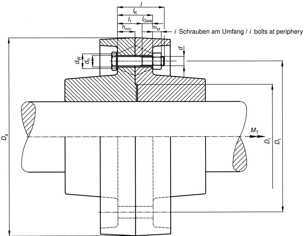 Bolted joint at a flange coupling (Source: VDI 2230 Part 1:2015, Figure B2, p. 137)
Inputs
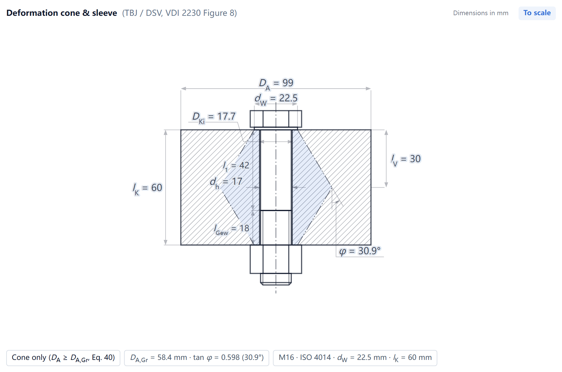 Geometry inputs of this example (drawn by the MechCalc calculator with this example loaded)
| Name | Symbol | Value |
|---|---|---|
| Clamped layers 1, Young’s modulus | $E_{P}$ | 110000 N/mm² |
| Clamped layers 1, Material | — | GJL-250 |
| Strength Class | — | 10.9 |
| Yield Strength † | $R_{p0{,}2}$ | 940 N/mm² |
| Tensile Strength | $R_m$ | 1000 N/mm² |
| Elastic Modulus | $E_S$ | 205000 N/mm² |
| Bolt size | $d$ | M16 |
| Bearing diameter from product data | $d_W$ | 22.5 mm |
| Clamped layers 1, Thickness | $h$ | 60 mm |
| Equivalent OD at the interface | $D_A$ | 99 mm |
| Through-hole Diameter | $d_h$ | 17 mm |
| Unthreaded shank length in the clamp | $l_1$ | 42 mm |
| Head-side bearing-face inner diameter (optional) | $D_{Ki}$ | 17.7 mm |
| Shear cross-section diameter (optional) | $d_\tau$ | 16 mm |
| Axial Load | $F_A$ | 0 N |
| Transverse Load | $F_Q$ | 8400 N |
| Load Introduction Factor † | $n$ | 0.5 |
| Required residual clamp load | $F_{KR,req}$ | 0 N |
| Calculation Mode | — | Verification Mode (specified) |
| Joint Type | — | TBJ — Through bolt/DSV |
| Head Type | — | Hexagon head (ISO 4014) |
| Calculate the clamped parts as a TBJ | — | Automatic (rule D_A ≤ 1.4 d_W) |
| Thread Friction | $\mu_{G,min}$ | 0.12 |
| Head Friction | $\mu_{K,min}$ | 0.12 |
| Interface Friction | $\mu_{T,min}$ | 0.15 |
| Number of force-transmitting inner interfaces | $q_F$ | 1 |
| Tightening Factor | $\alpha_A$ | 1.6 |
| Utilisation | $\nu$ | 0.9 |
| Embedding amount | — | From Table 5 (add up) |
| Surface roughness | $R_z$ | Rz < 10 μm |
| Load direction (Table 5) | — | Shear |
| Number of inner interfaces | — | 1 |
| Include Thermal Effects | — | No |
| Fatigue Check | — | No |
† Not given in the source: the bolt yield strength $R_{p0,2} = 940$ N/mm² is the minimum for strength grade 10.9 (DIN EN ISO 898-1:2013-05, 7, Table 3); the standard takes the permissible assembly preload directly from Table A1, which is based on 90 % use of this minimum yield strength (R7, p. 141). The load introduction factor $n = 0.5$ is the calculator default; the axial load is $F_A = 0$ here (R0, p. 137), so it changes no compared quantity or verdict.
Calculation Steps
Preload (R1–R6)
Step 4 R2: Required minimum clamp load $F_{Kerf}$ · VDI 2230, R2/1~R2/4 (Eq.108/109/111)
$$F_{KQ} = \frac{F_{Q\max}}{q_F\,\mu_{T\min}} + \frac{M_{Y\max}}{q_M\, r_a\, \mu_{T\min}}$$$$F_{Kerf} \geq \max(F_{KQ};\; F_{KP};\; F_{KR,req})$$Substitution: $F_{KQ} = 8400/(1 \cdot 0.15) = 56000\,\text{N}$ (friction)
$F_{KP} = 0\,\text{N}$ (sealing)
$F_{KR,req} = 0\,\text{N}$ (specified)
$F_{Kerf} = 56000\,\text{N}$
◆ Compared quantity Required clamp load $F_{Kerf}$ = 56000 N; example value 56000; error 0.00 % (see “Results Comparison”)
Step 5 R3a: Bolt axial resilience $\delta_S$ · VDI 2230 Blatt 1:2015, §5.1.1.1, Eq.(19)
$$\delta_S = \delta_{SK} + \delta_1 + \delta_{Gew} + \delta_{GM}$$Substitution: $\delta_S = 2.2484 \times 10^{-6}\,\text{mm/N}$ ($l_1 = 42.0\,\text{mm}$, $l_{Gew} = 18.0\,\text{mm}$, head: hex)
$l_{SK} = 0.5\,d$ (Eq.(30)) is given for the medium series of clearance holes (DIN EN 20273)
check the entered $d_h$ against that series
◆ Compared quantity Bolt resilience $\delta_S$ = $2.24839\times10^{-6}$ mm/N; example value $2.249\times10^{-6}$; error -0.03 % (see “Results Comparison”)
Step 6 R3b: Clamped-parts resilience $\delta_P$ · VDI 2230 Blatt 1:2015, §5.1.2.1, Eq.(40)
$$\delta_P=\frac{2\ln\left[\frac{(d_W+d_h)(d_W+w l_K\tan\varphi-d_h)}{(d_W-d_h)(d_W+w l_K\tan\varphi+d_h)}\right]}{w E_P\pi d_h\tan\varphi}$$Substitution: branch ② cone only ($D_A \geq D_{A,Gr}$)
$d_W = 22.50$, $D_A = 99.0$, $d_h = 17.0$, $w = 1$, $\tan\varphi = 0.5979$, $D_{A,Gr} = 58.37$ (mm) → $\delta_P = 7.8106 \times 10^{-7}\,\text{mm/N}$
◆ Compared quantity Clamped-part resilience $\delta_P$ = $7.81065\times10^{-7}$ mm/N; example value $7.81\times10^{-7}$; error +0.01 % (see “Results Comparison”)
Step 9 R4: Preload change · VDI 2230-1:2015, §5.4.2.1, Table 5
$$f_Z = \frac{f_{Z,thread} + n_{bearing} f_{Z,bearing} + n_{inner} f_{Z,inner}}{1000}$$$$F_Z = \frac{f_Z}{\delta_S + \delta_P}$$Substitution: Table 5, $R_z < 10\,\mu\text{m}$, shear: thread 3 μm
bearing areas 2 × 3 μm
inner interfaces 1 × 2 μm
total 11 μm = 0.011 mm
$F_Z = 0.011 / 3.0295 \times 10^{-6} = 3631\,\text{N}$
Table 5 applies to compact steel parts without coatings only
aluminium parts embed more (e.g. 10 μm instead of 5 μm at the thread of a tapped thread joint) (VDI 2230-1 §5.4.2.1)
above the limit surface pressure $p_G$ of Table A9 the Table 5 values are no longer valid
for a stack of thin plates measure $F_Z$ by test (VDI 2230-1 §5.4.2.1)
◆ Compared quantity Preload loss due to embedding $F_Z$ = 3631 N; example value 3630; error +0.03 % (see “Results Comparison”)
◆ Compared quantity Amount of embedding $f_Z$ = 11 μm; example value 11; error 0.00 % (see “Results Comparison”)
Step 10 R5: Minimum assembly preload $F_{M\min}$ · VDI 2230, R5/1
$$F_{M\min} = F_{Kerf} + (1-\Phi)\cdot F_A + F_Z + \Delta F'_{Vth}$$Substitution: $F_{M\min} = 56000 + (1-0.1289) \cdot 0 + 3631 + 0 = 59631\,\text{N}$
◆ Compared quantity Minimum assembly preload $F_{M\min}$ = 59631 N; example value 59630; error 0.00 % (see “Results Comparison”)
Step 11 R6: Maximum assembly preload $F_{M\max}$ · VDI 2230, R6/1
$$F_{M\max} = \alpha_A \cdot F_{M\min}$$Substitution: $F_{M\max} = 1.60 \cdot 59631 = 95410\,\text{N}$
◆ Compared quantity Maximum assembly preload $F_{Mmax}$ = 95410 N; example value 95408; error 0.00 % (see “Results Comparison”)
Checks (R7–R13)
Step 12 R7: Permissible assembly preload $F_{Mzul}$ · VDI 2230, R7/2
$$F_{Mzul} = A_0 \cdot \frac{\nu \cdot R_{p0{,}2}}{\sqrt{1+3\left[\frac{3}{2}\frac{d_2}{d_0}\left(\frac{P}{\pi d_2}+1.155\mu_{G\min}\right)\right]^2}}$$Substitution: $A_0 = 156.7\,\text{mm}^2$, $\nu = 0.9$, $R_{p0,2} = 940.0\,\text{N/mm}^2$ → $F_{Mzul} = 118928\,\text{N}$
◆ Compared quantity Permissible assembly preload $F_{Mzul}$ = 118928 N; example value 118800; error +0.11 % (see “Results Comparison”)
Step 16 R10: Surface pressure check (assembly and working state) · VDI 2230, R10/1 (Eq.190), R10/2 (Eq.191), R10/4; Eq.129/193/194; §5.5.4; Annex B, Example B4, R10 ✔
$$A_{p\min} = \tfrac{\pi}{4}(d_{Wa}^2 - D_{Ki}^2)$$$$p_{M\max} = \frac{F_{Mzul}}{A_{p\min}}$$$$p_{B\max} = \frac{F_{V\max} + F_{SA\max} - \Delta F_{Vth}}{A_{p\min}} \le p_G$$Substitution: Head side: $D_{Ki} = 17.70\,\text{mm}$, $d_{Wa} = 22.50\,\text{mm}$, $A_{p\min} = \tfrac{\pi}{4}(22.50^2 - 17.70^2) = 151.6\,\text{mm}^2$
$p_{M\max} = 784.7\,\text{N/mm}^2$ (R10/1 (Gl.190))
$p_{B\max} = (118928 + 0 - 0)/151.6 = 784.7\,\text{N/mm}^2$
head side $p_G = 850\,\text{N/mm}^2$ (Table A9 (GJL-250)): $S_p = 1.08$, $S_{pB} = 1.08$
Nut side: $d_{WMu} = 22.49\,\text{mm}$ ($d_{w,min}$ per ISO 4032 (DIN EN ISO 4032:2023-12)), $D_{Ki,Mu} = 17.28\,\text{mm}$ (nut side: $D_{Ki}$ not given, fell back to max($d_{a,max}$, $d_h$) — the bearing area is not reduced for the chamfer of the clamped part, $S_p$ is optimistic), $d_{Wa,Mu} = 22.49\,\text{mm}$, $A_{pMu,\min} = \tfrac{\pi}{4}(22.49^2 - 17.28^2) = 162.7\,\text{mm}^2$
$p_{Mu\max} = 730.8\,\text{N/mm}^2$
$p_{B\max,Mu} = 730.8\,\text{N/mm}^2$
nut side $p_G = 850\,\text{N/mm}^2$ (Table A9 (GJL-250)): $S_p = 1.16$, $S_{pB} = 1.16$
critical side: head
◆ Compared quantity Minimum bearing area $A_{p\min}$ (head side) = 151.6 mm²; example value 151.5; error +0.07 % (see “Results Comparison”)
◆ Compared quantity Surface pressure in the assembly state $p_{M\max}$ (head side) = 784.7 N/mm²; example value 784; error +0.09 % (see “Results Comparison”)
◆ Compared quantity Surface pressure check (assembly state): $S_P$ reaches the required value (R10) = Yes; example value Yes; error Match (see “Results Comparison”)
Step 17 R12: Safety margin against slipping $S_G$ · VDI 2230 Blatt 1:2015, R12/1, R12/2 (Eq.108), R12/4 ✔
$$F_{KQ,erf} = \frac{F_{Q\max}}{q_F\,\mu_{T\min}} + \frac{M_{Y\max}}{q_M\,r_a\,\mu_{T\min}}$$$$S_G = \frac{F_{KR\min}}{F_{KQ,erf}} > 1.0$$Substitution: $F_{KQ,erf} = 8400/(1 \cdot 0.15) = 56000\,\text{N}$
$F_{KR\min} = 70699\,\text{N}$ → $S_G = 1.26$ ✅
required $S_G \ge 1.2$ (static loading, normal value of R12/4; the safety margin is set by the user)
◆ Compared quantity Minimum residual clamp load $F_{KR\min}$ = 70699 N; example value 70620; error +0.11 % (see “Results Comparison”)
◆ Compared quantity Safety margin against slipping $S_G$ = 1.26; example value 1.26; error 0.00 % (see “Results Comparison”)
◆ Compared quantity Slip check: $S_G$ reaches the required value (R12) = Yes; example value Yes; error Match (see “Results Comparison”)
Step 18 R12b: Bolt shear $S_A$ · VDI 2230 Blatt 1:2015, §5.5.6.3, Eq.(219)(220) ✔
$$A_\tau=\frac{\pi}{4}d_\tau^2$$$$S_A=\frac{\tau_{BS}}{\tau_{Qmax}}\geq1.1$$Substitution: $d_\tau = 16.000\,\text{mm}$
$A_\tau = 201.1\,\text{mm}^2$
$\tau_{BS} = 0.62 \cdot 1000.0 = 620\,\text{N/mm}^2$
$\tau_{Q\max} = 8400/201.1 = 41.8\,\text{N/mm}^2$
$S_A = 14.84$
◆ Compared quantity Maximum shear stress $\tau_{Q\max}$ = 41.8 N/mm²; example value 41.8; error 0.00 % (see “Results Comparison”)
◆ Compared quantity Shear check: $S_A$ reaches the required value (R12) = Yes; example value Yes; error Match (see “Results Comparison”)
Step 21 R13: Tightening torque $M_A$ · VDI 2230, R13/1 (Eq.127), Eq.128/129
$$D_{Km} = \frac{d_W + D_{Ki}}{2}$$$$M_A = F_{Mzul}\left[0.16P + 0.58 d_2 \mu_{G\min} + \frac{D_{Km}}{2}\mu_{K\min}\right]$$Substitution: $D_{Km} = (22.50 + 17.70)/2 = 20.10\,\text{mm}$
$M_A = 118928 \cdot [0.16 \cdot 2.0 + 0.58 \cdot 14.701 \cdot 0.12 + 20.10/2 \cdot 0.12] = 303171\,\text{N}\cdot\text{mm} = 303.2\,\text{N}\cdot\text{m}$
◆ Compared quantity Tightening torque $M_A$ = 303171 N·mm; example value 302000; error +0.39 % (see “Results Comparison”)
Results Comparison
| Results | Example | MechCalc | Error (%) |
|---|---|---|---|
| Required clamp load $F_{Kerf}$ (N) (Step 4) | 56000 | 56000 | 0.00 |
| Bolt resilience $\delta_S$ (mm/N) (Step 5) | $2.249\times10^{-6}$ | $2.24839\times10^{-6}$ | -0.03 |
| Clamped-part resilience $\delta_P$ (mm/N) (Step 6) | $7.81\times10^{-7}$ | $7.81065\times10^{-7}$ | +0.01 |
| Preload loss due to embedding $F_Z$ (N) (Step 9) | 3630 | 3631 | +0.03 |
| Minimum assembly preload $F_{M\min}$ (N) (Step 10) | 59630 | 59631 | 0.00 |
| Maximum assembly preload $F_{Mmax}$ (N) (Step 11) | 95408 | 95410 | 0.00 |
| Minimum bearing area $A_{p\min}$ (head side) (mm²) (Step 16) | 151.5 | 151.6 | +0.07 |
| Maximum shear stress $\tau_{Q\max}$ (N/mm²) (Step 18) | 41.8 | 41.8 | 0.00 |
| Amount of embedding $f_Z$ (μm) (Step 9) | 11 | 11 | 0.00 |
| Permissible assembly preload $F_{Mzul}$ (N) (Step 12) | 118800 | 118928 | +0.11 |
| Surface pressure in the assembly state $p_{M\max}$ (head side) (N/mm²) (Step 16) | 784 | 784.7 | +0.09 |
| Minimum residual clamp load $F_{KR\min}$ (N) (Step 17) | 70620 | 70699 | +0.11 |
| Safety margin against slipping $S_G$ (Step 17) | 1.26 | 1.26 | 0.00 |
| Tightening torque $M_A$ (N·mm) (Step 21) | 302000 | 303171 | +0.39 |
| Shear check: $S_A$ reaches the required value (R12) (Step 18) | Yes | Yes | Match |
| Surface pressure check (assembly state): $S_P$ reaches the required value (R10) (Step 16) | Yes | Yes | Match |
| Slip check: $S_G$ reaches the required value (R12) (Step 17) | Yes | Yes | Match |