Source: Verein Deutscher Ingenieure. (2015). VDI 2230 Part 1: Systematic calculation of highly stressed bolted joints – Joints with one cylindrical bolt (German/English ed., November 2015). Düsseldorf: VDI; Berlin: Beuth. Annex B, Example B3, Calculation of a flywheel assembly with a central bolt as an example of bolt stress with torsional shearing force, pp. 142–149, Figure B3 and Table B1
Calculator: VDI 2230-1 Single-bolt Joint Calculation loads all inputs of this example; press Run Calculation to recompute.
Problem
One special hexagon hollow bolt M27×2 of strength grade 8.8 (24 mm shank, 16 mm bore) fixes a flywheel to the end of a crankshaft. It presses the flywheel through a 1.5 mm E 295 washer and is screwed into an internal thread in the crankshaft end (tapped thread joint), with clamping length $l_K = 16$ mm. The joint must carry 110 N·m of torque by friction; on the safe side, all of it is taken through a contact ring of 30 mm inside and 48 mm outside diameter on the crankshaft end. Flywheel and crankshaft are 16MnCr5, there is no axial working load, and tightening is with a measuring precision torque wrench (pp. 142–145).
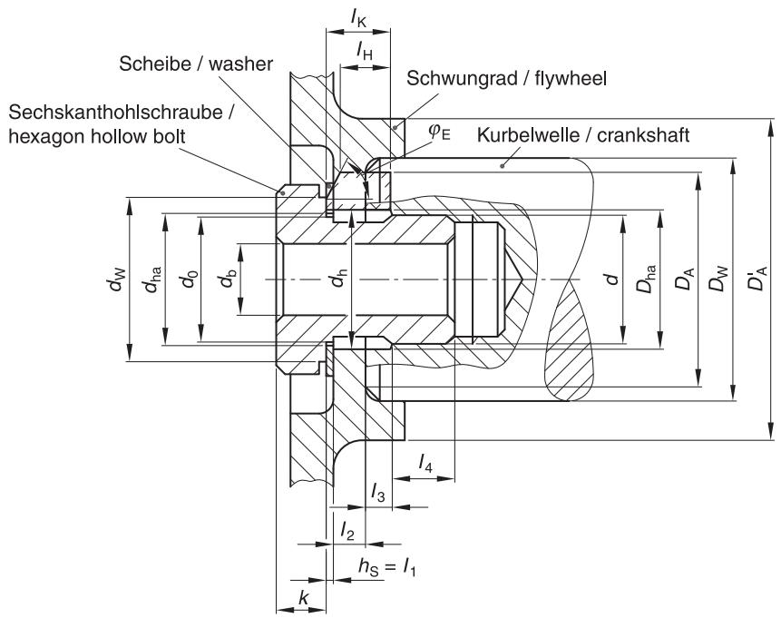 Flywheel assembly with a central bolt (Source: VDI 2230 Part 1:2015, Figure B3, p. 143)
Inputs
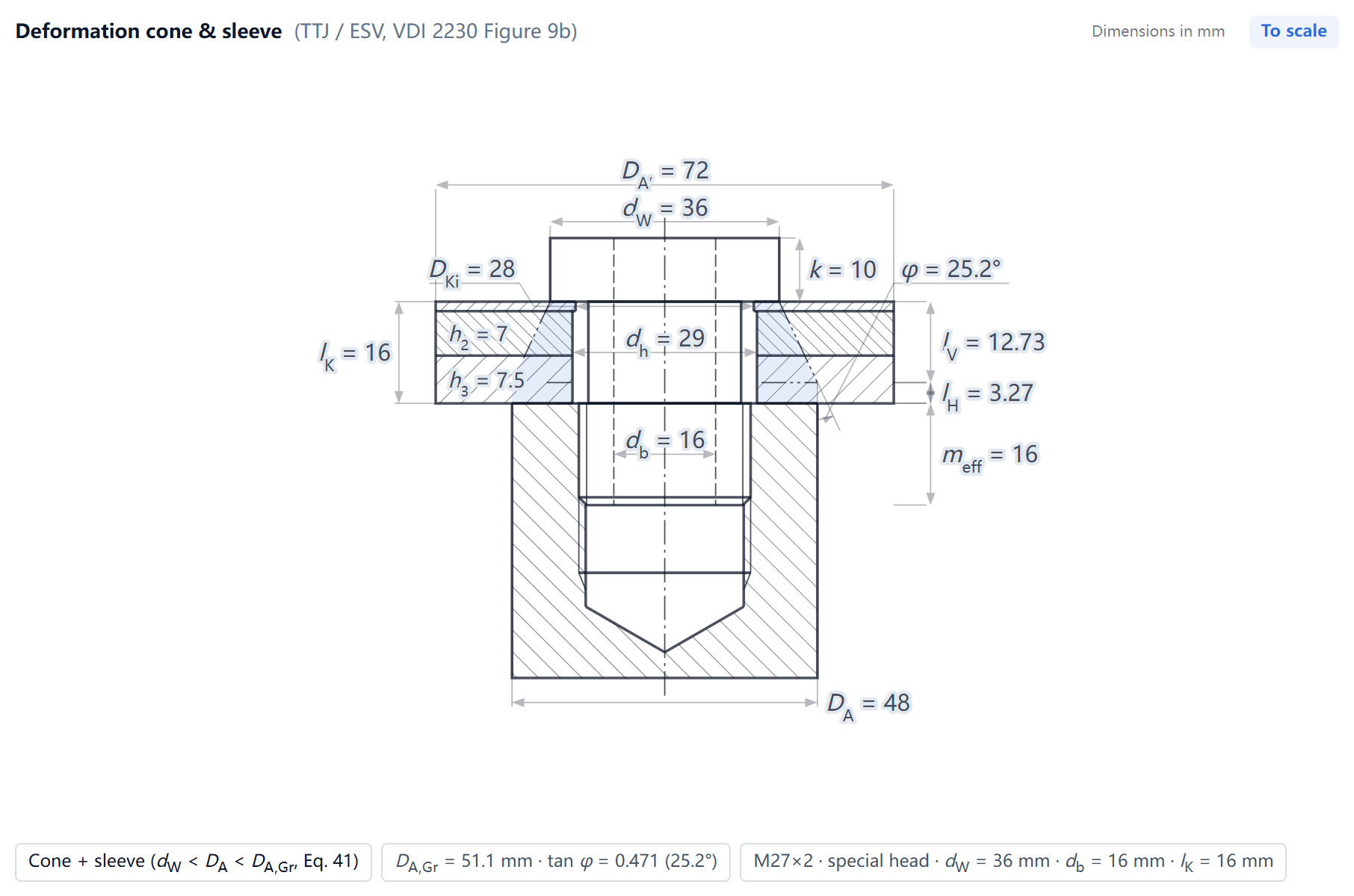 Geometry inputs of this example (drawn by the MechCalc calculator with this example loaded)
| Name | Symbol | Value |
|---|---|---|
| Clamped layers 1, Young’s modulus | $E_{P}$ | 205000 N/mm² |
| Clamped layers 1, Material | — | E295 |
| Clamped layers 2, Young’s modulus | $E_{P}$ | 205000 N/mm² |
| Clamped layers 3, Young’s modulus | $E_{P}$ | 205000 N/mm² |
| Nut/internal-thread tensile strength | $R_{mM}$ | 1000 N/mm² |
| Strength Class | — | 8.8 |
| Yield Strength | $R_{p0{,}2}$ | 660 N/mm² |
| Tensile Strength | $R_m$ | 830 N/mm² |
| Elastic Modulus | $E_S$ | 205000 N/mm² |
| Tapped-body modulus (optional) | $E_{BI}$ | 205000 N/mm² |
| Bolt size | $d$ | M27 |
| Fine pitch (optional) | $P$ | 2 mm |
| Bearing diameter from product data | $d_W$ | 36 mm |
| Special head height (for the sketch only) | $k$ | 10 mm |
| Bore of a hollow bolt | $d_b$ | 16 mm |
| Clamped layers 1, Thickness | $h$ | 1.5 mm |
| Clamped layers 2, Thickness | $h$ | 7 mm |
| Clamped layers 3, Thickness | $h$ | 7.5 mm |
| Equivalent OD at the interface | $D_A$ | 48 mm |
| Equivalent OD of the base body (optional) | $D_A'$ | 72 mm |
| Through-hole Diameter | $d_h$ | 29 mm |
| Available length of engagement (optional) † | $m_{eff,vorh}$ | 16 mm |
| Bolt segments 1, Length | $l$ | 16 mm |
| Bolt segments 1, Diameter | $d$ | 24 mm |
| Head-side bearing-face inner diameter (optional) | $D_{Ki}$ | 28 mm |
| Equivalent diameter around the internal thread | $s$ | 50 mm |
| Bolt major diameter, lower limit | $d_{min}$ | 26.682 mm |
| Bolt pitch diameter, lower limit | $d_{2min}$ | 25.493 mm |
| Internal minor diameter, upper limit | $D_{1max}$ | 25.21 mm |
| Friction radius for $M_Y$ (required if $M_Y>0$) | $r_a$ | 19.5 mm |
| Axial Load | $F_A$ | 0 N |
| Transverse Load | $F_Q$ | 0 N |
| Load Introduction Factor | $n$ | 1 |
| Torque about the bolt axis | $M_Y$ | 110000 N·mm |
| Required residual clamp load | $F_{KR,req}$ | 0 N |
| Min. Axial Load | $F_{A,min}$ | 0 N |
| Calculation Mode | — | Verification Mode (specified) |
| Joint Type | — | TTJ — Tapped hole/ESV |
| Head Type | — | Special head (enter the bearing diameter) |
| Calculate the clamped parts as a TBJ | — | No |
| Bolt segments 1, Segment type | — | Custom $d$ |
| Thread Friction | $\mu_{G,min}$ | 0.12 |
| Head Friction | $\mu_{K,min}$ | 0.1 |
| Interface Friction | $\mu_{T,min}$ | 0.1 |
| Number of force-transmitting inner interfaces † | $q_F$ | 1 |
| Number of torque-transmitting inner interfaces | $q_M$ | 1 |
| Tightening Method | — | Torque controlled (αA from Table A8, default 1.6) |
| Tightening Factor | $\alpha_A$ | 1.6 |
| Utilisation | $\nu$ | 0.9 |
| Embedding amount | — | From Table 5 (add up) |
| Surface roughness | $R_z$ | 10 ≤ Rz < 40 μm |
| Load direction (Table 5) | — | Shear |
| Number of inner interfaces | — | 2 |
| Include Thermal Effects | — | No |
| Fatigue Check | — | No |
† Not given in the source: the available effective length of engagement $m_{eff,vorh} = 16$ mm is the usable thread length $l_4 = 20$ mm minus $2P = 4$ mm (Table B1, p. 143; the $2P$ deduction as in Eq. (208)); in R11 the standard uses the thread contact length of 18.5 mm after a chamfer of about 1.5 mm (p. 148), and both give enough engagement. The number of slipping interfaces $q_F = 1$ is the calculator default; the transverse load is 0 here, so it changes no compared quantity or verdict.
Calculation Steps
Preload (R1–R6)
Step 5 R2: Required minimum clamp load $F_{Kerf}$ · VDI 2230, R2/1~R2/4 (Eq.108/109/111)
$$F_{KQ} = \frac{F_{Q\max}}{q_F\,\mu_{T\min}} + \frac{M_{Y\max}}{q_M\, r_a\, \mu_{T\min}}$$$$F_{Kerf} \geq \max(F_{KQ};\; F_{KP};\; F_{KR,req})$$Substitution: $F_{KQ} = 110000/(1 \cdot 19.5 \cdot 0.1) = 56410\,\text{N}$ (friction)
$F_{KP} = 0\,\text{N}$ (sealing)
$F_{KR,req} = 0\,\text{N}$ (specified)
$F_{Kerf} = 56410\,\text{N}$
◆ Compared quantity Required clamp load $F_{Kerf}$ = 56410.3 N; example value 56400; error +0.02 % (see “Results Comparison” [1])
Step 6 R3a: Bolt axial resilience $\delta_S$ · VDI 2230 Blatt 1:2015, §5.1.1.1, Figure 6, Eq.(18)(19)
$$\delta_S = \delta_{SK} + \sum_i \frac{l_i}{E_S A_i} + \delta_{GM}$$$$\delta_i = \frac{l_i}{E_S A_i}$$Substitution: 1 segment(s): $\delta_{1} = 3.105 \times 10^{-7}$ ($l = 16\,\text{mm}$, custom, $d = 24.000\,\text{mm}$, $A_i = \pi/4\,(d_i^2 - d_b^2)$ (Gl.18, hollow))
$\delta_{SK} = 1.773 \times 10^{-7}$, $\delta_{GM} = 3.179 \times 10^{-7}$ → $\delta_S = 8.0570 \times 10^{-7}\,\text{mm/N}$ (head: custom)
$\delta_M$ uses $E_M = E_{BI} = 205000\,\text{N/mm}^2$
$l_{SK} = 0.5\,d$ (Eq.(30)) is given for the medium series of clearance holes (DIN EN 20273)
check the entered $d_h$ against that series
◆ Compared quantity Bolt resilience $\delta_S$ = $8.05696\times10^{-7}$ mm/N; example value $8.0566\times10^{-7}$; error 0.00 % (see “Results Comparison” [1])
Step 11 R4: Preload change · VDI 2230-1:2015, §5.4.2.1, Table 5
$$f_Z = \frac{f_{Z,thread} + n_{bearing} f_{Z,bearing} + n_{inner} f_{Z,inner}}{1000}$$$$F_Z = \frac{f_Z}{\delta_S + \delta_P}$$Substitution: Table 5, $10 \leq R_z < 40\,\mu\text{m}$, shear: thread 3 μm
bearing areas 1 × 4.5 μm
inner interfaces 2 × 2.5 μm
total 12.5 μm = 0.0125 mm
$F_Z = 0.0125 / 9.1377 \times 10^{-7} = 13680\,\text{N}$
Table 5 applies to compact steel parts without coatings only
aluminium parts embed more (e.g. 10 μm instead of 5 μm at the thread of a tapped thread joint) (VDI 2230-1 §5.4.2.1)
above the limit surface pressure $p_G$ of Table A9 the Table 5 values are no longer valid
for a stack of thin plates measure $F_Z$ by test (VDI 2230-1 §5.4.2.1)
◆ Compared quantity Amount of embedding $f_Z$ = 12.5 μm; example value 12.5; error 0.00 % (see “Results Comparison” [1])
◆ Compared quantity Preload loss due to embedding $F_Z$ = 13680 N; example value 13700; error -0.15 % (see “Results Comparison” [2])
Step 12 R5: Minimum assembly preload $F_{M\min}$ · VDI 2230, R5/1
$$F_{M\min} = F_{Kerf} + (1-\Phi)\cdot F_A + F_Z + \Delta F'_{Vth}$$Substitution: $F_{M\min} = 56410 + (1-0.2013) \cdot 0 + 13680 + 0 = 70090\,\text{N}$
◆ Compared quantity Minimum assembly preload $F_{M\min}$ = 70090 N; example value 70100; error -0.01 % (see “Results Comparison” [2])
Step 13 R6: Maximum assembly preload $F_{M\max}$ · VDI 2230, R6/1
$$F_{M\max} = \alpha_A \cdot F_{M\min}$$Substitution: $F_{M\max} = 1.60 \cdot 70090 = 112144\,\text{N}$
◆ Compared quantity Maximum assembly preload $F_{Mmax}$ = 112144 N; example value 112200; error -0.05 % (see “Results Comparison” [2])
Checks (R7–R13)
Step 14 R7: Permissible assembly preload $F_{Mzul}$ · VDI 2230 Blatt 1:2015, Annex B, Example B3, R7; Eq.(140), (143), (144)
$$F_{Mzul} = A_0 \cdot \frac{\nu \cdot R_{p0{,}2}}{\sqrt{1+3\left[\frac{3}{2}\frac{d_2\left(d_0^2-d_b^2\right)}{d_0^3-d_b^3}\left(\frac{P}{\pi d_2}+1.155\mu_{G\min}\right)\right]^2}}$$Substitution: $d_0 = d_i = 24.000\,\text{mm}$ (weakest segment)
$A_0 = \frac{\pi}{4}(24.000^2 - 16.000^2) = 251.33\,\text{mm}^2$ (hollow)
necked-down bolt: $d_0 = d_{i,min}$ per §5.5.1
$\nu = 0.9$, $R_{p0,2} = 660.0\,\text{N/mm}^2$ → $F_{Mzul} = 140516\,\text{N}$
hollow bolt: equation derived in VDI 2230 Part 1:2015, Annex B, Example B3, R7 by analogy with Eq.(140) — not a main-text equation
◆ Compared quantity Relevant section area $A_0$ = 251.327 mm²; example value 251; error +0.13 % (see “Results Comparison” [1])
◆ Compared quantity Permissible assembly preload $F_{Mzul}$ = 140516 N; example value 140300; error +0.15 % (see “Results Comparison” [1])
Step 18 R10: Surface pressure check (assembly and working state) · VDI 2230, R10/1 (Eq.190), R10/2 (Eq.191), R10/4; Eq.129/193/194; §5.5.4 ✔
$$A_{p\min} = \tfrac{\pi}{4}(d_{Wa}^2 - D_{Ki}^2)$$$$p_{M\max} = \frac{F_{Mzul}}{A_{p\min}}$$$$p_{B\max} = \frac{F_{V\max} + F_{SA\max} - \Delta F_{Vth}}{A_{p\min}} \le p_G$$Substitution: $D_{Ki} = 28.00\,\text{mm}$
$D_{Ki} < d_h$: the head bears on a part with a smaller bore (e.g. a washer), $d_{Wa} = 36.00\,\text{mm}$, $A_{p\min} = \tfrac{\pi}{4}(36.00^2 - 28.00^2) = 402.1\,\text{mm}^2$
$p_{M\max} = 349.4\,\text{N/mm}^2$ (R10/1 (Gl.190))
$p_{B\max} = (140516 + 0 - 0)/402.1 = 349.4\,\text{N/mm}^2$
head side $p_G = 710\,\text{N/mm}^2$ (Table A9 (E295)): $S_p = 2.03$, $S_{pB} = 2.03$
◆ Compared quantity Minimum bearing area $A_{p\min}$ (head side) = 402.1 mm²; example value 402.1; error 0.00 % (see “Results Comparison” [1])
◆ Compared quantity Surface pressure in the assembly state $p_{M\max}$ (head side) = 349.4 N/mm²; example value 348.9; error +0.14 % (see “Results Comparison” [1])
◆ Compared quantity Safety margin against surface pressure in the assembly state $S_P$ = 2.03; example value 2; error +1.50 % (see “Results Comparison” [1])
◆ Compared quantity Surface pressure check (assembly state): $S_P$ reaches the required value (R10) = Yes; example value Yes; error Match (see “Results Comparison”)
Step 19 R11a: Strength ratio $R_S$ & critical thread · VDI 2230 Blatt 1:2015, §5.5.5, Eq.(199)
$$R_S=\frac{d[P/2+(d-D_2)\tan30°]}{D_1[P/2+(d_2-D_1)\tan30°]}\cdot\frac{R_{mM}}{R_{mS}}$$Substitution: $R_S = 1.5282$ → bolt thread critical (§5.5.5.2)
$s/d = 1.852$ → Eq.(201)
$C_2 = 1.1146$ (Gl.211)
◆ Compared quantity Strength ratio $R_S$ = 1.5282; example value 1.52; error +0.54 % (see “Results Comparison” [1])
◆ Compared quantity Correction factor $C_2$ (bolt thread) = 1.1146; example value 1.1; error +1.33 % (see “Results Comparison” [1])
Step 20 R11c: Required length of engagement (bolt thread critical) · VDI 2230 Blatt 1:2015, §5.5.5.2, Eq.(211)–(213), Table 7
$$m_{ges,min}=\frac{F_{mS}P}{C_1C_2\tau_{BS,min}[P/2+(d_{2min}-D_{1max})\tan30°]\pi d_{min}}+2P$$Substitution: hollow bolt: $R_{m,max}A_S := F_{Mzul}$ (Annex B, Example B3)
$\tau_{BS,min} = 0.65\times830.0 = 539.5\,\text{N/mm}^2$ (Table 7)
$m_{ges,\min} = 8.803\,\text{mm}$, $m_{eff,\min} = m_{ges,\min} - 2P = 4.803\,\text{mm}$
hollow bolt: §5.5.5 applies to solid-shank bolts, the length of engagement can be calculated only as an estimate and only a practical test will bring certainty (VDI 2230 Part 1:2015, Annex B, Example B3, R11)
◆ Compared quantity Correction factor $C_1$ = 0.9977; example value 1; error -0.23 % (see “Results Comparison” [1])
◆ Compared quantity Minimum shearing strength of the thread used in R11, $\tau_{BS,\min}$ or $\tau_{BM,\min}$ (the side that fails first) = 539.5 N/mm²; example value 540; error -0.09 % (see “Results Comparison” [1])
Step 21 R11: Length of engagement check (TTJ) · VDI 2230, R11/1, Figure 36 ✔
$$m_{eff,vorh} \geq m_{eff,\min}$$Substitution: $m_{eff,\min} = 4.803\,\text{mm}$ (analytic, tolerance limits given, see R11b/R11c above)
$m_{eff,vorh} = 16.0\,\text{mm}$ → OK
◆ Compared quantity Length of engagement check: the available $m_{eff}$ reaches the required value (R11) = Yes; example value Yes; error Match (see “Results Comparison” [3])
Step 22 R12: Safety margin against slipping $S_G$ · VDI 2230 Blatt 1:2015, R12/1, R12/2 (Eq.108), R12/4 ✔
$$F_{KQ,erf} = \frac{F_{Q\max}}{q_F\,\mu_{T\min}} + \frac{M_{Y\max}}{q_M\,r_a\,\mu_{T\min}}$$$$S_G = \frac{F_{KR\min}}{F_{KQ,erf}} > 1.0$$Substitution: $F_{KQ,erf} = 110000/(1 \cdot 19.5 \cdot 0.1) = 56410\,\text{N}$
$F_{KR\min} = 74143\,\text{N}$ → $S_G = 1.31$ ✅
required $S_G \ge 1.2$ (static loading, normal value of R12/4; the safety margin is set by the user)
◆ Compared quantity Minimum residual clamp load $F_{KR\min}$ = 74143 N; example value 74000; error +0.19 % (see “Results Comparison” [2])
◆ Compared quantity Safety margin against slipping $S_G$ = 1.31; example value 1.31; error 0.00 % (see “Results Comparison” [2])
◆ Compared quantity Slip check: $S_G$ reaches the required value (R12) = Yes; example value Yes; error Match (see “Results Comparison” [3])
Step 23 R13: Tightening torque $M_A$ · VDI 2230, R13/1 (Eq.127), Eq.128/129
$$D_{Km} = \frac{d_W + D_{Ki}}{2}$$$$M_A = F_{Mzul}\left[0.16P + 0.58 d_2 \mu_{G\min} + \frac{D_{Km}}{2}\mu_{K\min}\right]$$Substitution: $D_{Km} = (36.00 + 28.00)/2 = 32.00\,\text{mm}$
$M_A = 140516 \cdot [0.16 \cdot 2.0 + 0.58 \cdot 25.701 \cdot 0.12 + 32.00/2 \cdot 0.1] = 521142\,\text{N}\cdot\text{mm} = 521.1\,\text{N}\cdot\text{m}$
◆ Compared quantity Effective friction diameter $D_{Km}$ = 32 mm; example value 32; error 0.00 % (see “Results Comparison” [1])
◆ Compared quantity Tightening torque $M_A$ = 521142 N·mm; example value 520000; error +0.22 % (see “Results Comparison” [1])
Results Comparison
| Results | Example | MechCalc | Error (%) |
|---|---|---|---|
| Required clamp load $F_{Kerf}$ (N) (Step 5) | 56400 | 56410.3 | +0.02 [1] |
| Bolt resilience $\delta_S$ (mm/N) (Step 6) | $8.0566\times10^{-7}$ | $8.05696\times10^{-7}$ | 0.00 [1] |
| Relevant section area $A_0$ (mm²) (Step 14) | 251 | 251.327 | +0.13 [1] |
| Permissible assembly preload $F_{Mzul}$ (N) (Step 14) | 140300 | 140516 | +0.15 [1] |
| Minimum bearing area $A_{p\min}$ (head side) (mm²) (Step 18) | 402.1 | 402.1 | 0.00 [1] |
| Surface pressure in the assembly state $p_{M\max}$ (head side) (N/mm²) (Step 18) | 348.9 | 349.4 | +0.14 [1] |
| Safety margin against surface pressure in the assembly state $S_P$ (Step 18) | 2 | 2.03 | +1.50 [1] |
| Strength ratio $R_S$ (Step 19) | 1.52 | 1.5282 | +0.54 [1] |
| Correction factor $C_1$ (Step 20) | 1 | 0.9977 | -0.23 [1] |
| Correction factor $C_2$ (bolt thread) (Step 19) | 1.1 | 1.1146 | +1.33 [1] |
| Minimum shearing strength of the thread used in R11, $\tau_{BS,\min}$ or $\tau_{BM,\min}$ (the side that fails first) (N/mm²) (Step 20) | 540 | 539.5 | -0.09 [1] |
| Effective friction diameter $D_{Km}$ (mm) (Step 23) | 32 | 32 | 0.00 [1] |
| Tightening torque $M_A$ (N·mm) (Step 23) | 520000 | 521142 | +0.22 [1] |
| Amount of embedding $f_Z$ (μm) (Step 11) | 12.5 | 12.5 | 0.00 [1] |
| Preload loss due to embedding $F_Z$ (N) (Step 11) | 13700 | 13680 | -0.15 [2] |
| Minimum assembly preload $F_{M\min}$ (N) (Step 12) | 70100 | 70090 | -0.01 [2] |
| Maximum assembly preload $F_{Mmax}$ (N) (Step 13) | 112200 | 112144 | -0.05 [2] |
| Minimum residual clamp load $F_{KR\min}$ (N) (Step 22) | 74000 | 74143 | +0.19 [2] |
| Safety margin against slipping $S_G$ (Step 22) | 1.31 | 1.31 | 0.00 [2] |
| Surface pressure check (assembly state): $S_P$ reaches the required value (R10) (Step 18) | Yes | Yes | Match |
| Length of engagement check: the available $m_{eff}$ reaches the required value (R11) (Step 21) | Yes | Yes | Match [3] |
| Slip check: $S_G$ reaches the required value (R12) (Step 22) | Yes | Yes | Match [3] |
- [1] In R11 (p. 148), after finding the bolt thread critical, the standard says to continue with Equations (200), (210) and (212); in the main text $C_1$ is Eq. (201), and for $R_S = 1.52$ $C_2$ comes from Eq. (211) (valid for $1 < R_S < 2.2$; Eq. (212) is only for $R_S \ge 2.2$). The standard in fact uses the polynomial of Eq. (211) and gets $C_2 = 1.1$, so this is only a slip in the references and no number or pass/fail verdict is affected.
- [2] In R3 (p. 145) the standard prints $\delta_P = 0.1055\cdot10^{-6}$ mm/N, but Eq. (41) with the $E_P = 2.05\cdot10^5$ N/mm² printed on the same page gives $0.1081\cdot10^{-6}$ (+2.4 %); the printed value matches $E_P = 2.1\cdot10^5$, and R4 (p. 146) then uses $0.10557\cdot10^{-6}$. So $\delta_P$ is not used as an example value; the quantities in this item come from it, $F_Z$ shifts by about 0.3 % and the others by less, with no change in any verdict. On the same page the shape check of the deformation body cites Equation (29), which is Eq. (39) in the main text, a slip in the reference only. In R12 (p. 148) the English column prints $S_G = 1.33$; the German column gives 1.31, which matches $74/56.4 = 1.31$ and is used here. Table B1 (p. 143) prints $D_A = 72$ mm in the row of the clamped parts; it should be $D'_A$, which is what R3 uses.
- [3] In R11 (p. 148) the standard ends the formula for $m_{ges,min}$ with $+1.2\cdot P$ and gets 7.25 mm; Eq. (213) of the main text (Section 5.5.5) ends with $+2P$, which gives about 8.8 mm, and the standard does not say why it uses 1.2P. The calculator follows Eq. (213); both values are far below the available length of engagement, so both pass.