Source: Verein Deutscher Ingenieure. (2015). VDI 2230 Part 1: Systematic calculation of highly stressed bolted joints – Joints with one cylindrical bolt (German/English ed., November 2015). Düsseldorf: VDI; Berlin: Beuth. Annex B, Example B1, Calculation of a bolted joint between a piston and a piston rod in a hydraulic cylinder as an example of concentric clamping and concentric loading, pp. 130–136, Figure B1
Calculator: VDI 2230-1 Single-bolt Joint Calculation loads all inputs of this example; press Run Calculation to recompute.
Problem
In the hydraulic cylinder of a press (300 working strokes per hour), one socket head cap screw M12×60 of strength grade 10.9 fixes the piston to the piston rod. It passes through the piston (16MnCr5) into a tapped hole in the rod end (C45): a tapped thread joint with clamping length $l_K = 42$ mm. A pressure of up to $p_{\max} = 5.5$ N/mm² acts on a ring of 80 mm outside and 25 mm inside diameter, so the axial working load pulses between 0 and $F_{A\max} = 24.9$ kN. The screw also seals, so at least 1000 N of residual clamp load must remain. Tightening is with an indicating torque wrench (pp. 130–131).
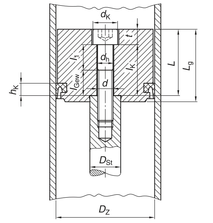 Hydraulic cylinder with a central bolted joint between piston and piston rod (Source: VDI 2230 Part 1:2015, Figure B1, p. 130)
Inputs
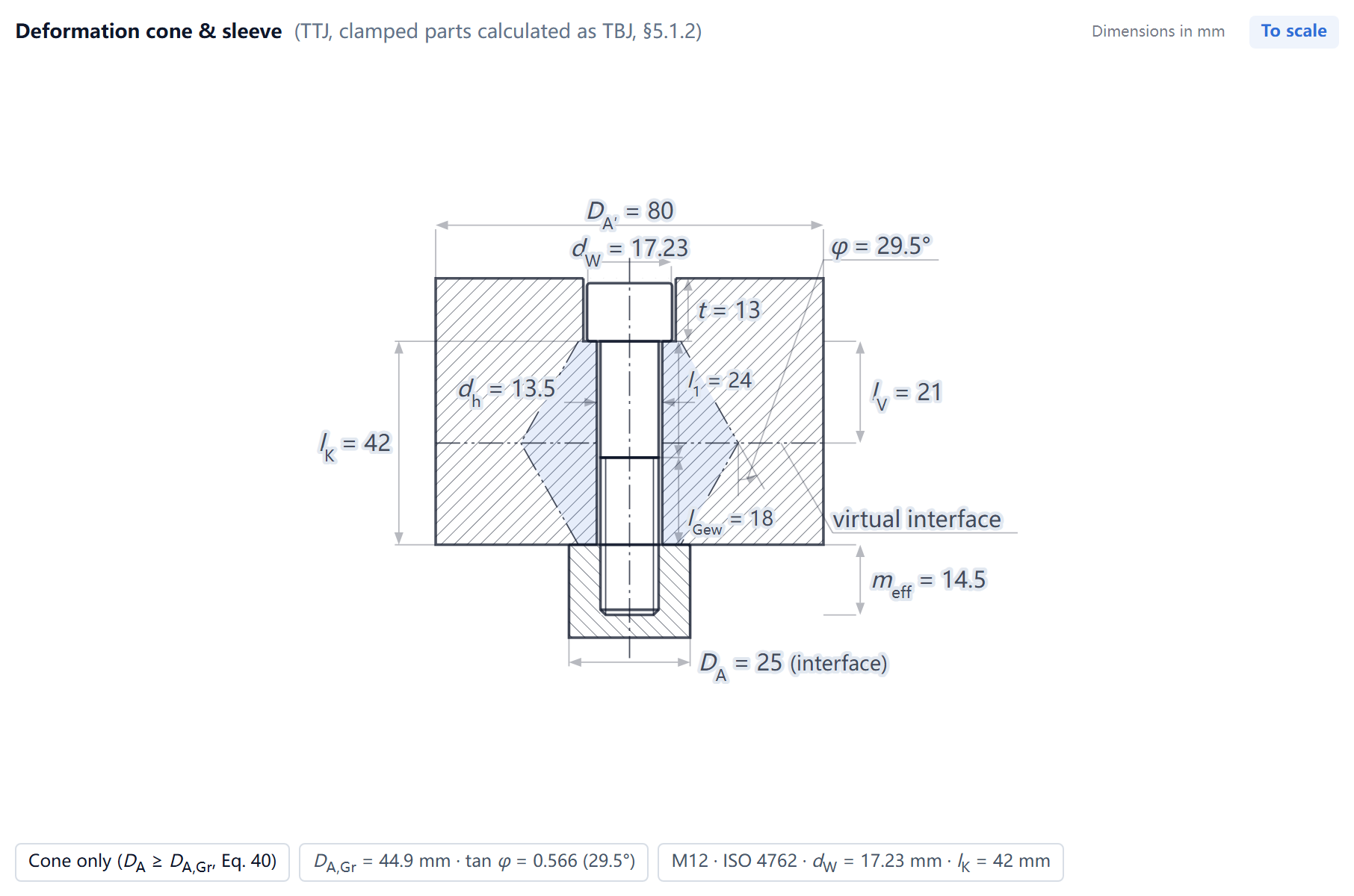 Geometry inputs of this example (drawn by the MechCalc calculator with this example loaded)
| Name | Symbol | Value |
|---|---|---|
| Clamped layers 1, Young’s modulus | $E_{P}$ | 205000 N/mm² |
| Clamped layers 1, Material | — | 16MnCr5 |
| Clamped layers 1, Limiting surface pressure | $p_{G}$ | 1300 N/mm² |
| Nut/internal-thread tensile strength | $R_{mM}$ | 700 N/mm² |
| Strength Class | — | 10.9 |
| Yield Strength | $R_{p0{,}2}$ | 940 N/mm² |
| Tensile Strength | $R_m$ | 1040 N/mm² |
| Elastic Modulus | $E_S$ | 205000 N/mm² |
| Bolt size | $d$ | M12 |
| Clamped layers 1, Thickness | $h$ | 42 mm |
| Equivalent OD at the interface | $D_A$ | 25 mm |
| Equivalent OD of the base body (optional) | $D_A'$ | 80 mm |
| Through-hole Diameter | $d_h$ | 13.5 mm |
| Unthreaded shank length in the clamp | $l_1$ | 24 mm |
| Available length of engagement (optional) | $m_{eff,vorh}$ | 14.5 mm |
| Distance bearing face → load point (optional) | $a_k$ | 3.89 mm |
| Length basic solid → load point (optional) | $l_A$ | 0 mm |
| Axial Load | $F_A$ | 24900 N |
| Transverse Load | $F_Q$ | 0 N |
| Load Introduction Factor | $n$ | 0.35 |
| Required residual clamp load | $F_{KR,req}$ | 1000 N |
| Min. Axial Load | $F_{A,min}$ | 0 N |
| Calculation Mode | — | Verification Mode (specified) |
| Joint Type | — | TTJ — Tapped hole/ESV |
| Head Type | — | Socket cap head (ISO 4762) |
| Calculate the clamped parts as a TBJ | — | Yes (my judgement, as in Example B1) |
| Joint type for load introduction (optional) | — | SV 4 |
| Thread Friction | $\mu_{G,min}$ | 0.1 |
| Head Friction | $\mu_{K,min}$ | 0.1 |
| Interface Friction † | $\mu_{T,min}$ | 0.1 |
| Number of force-transmitting inner interfaces † | $q_F$ | 1 |
| Tightening Factor | $\alpha_A$ | 1.8 |
| Utilisation | $\nu$ | 0.9 |
| Embedding amount | — | From Table 5 (add up) |
| Surface roughness | $R_z$ | 10 ≤ Rz < 40 μm |
| Load direction (Table 5) | — | Tension / compression |
| Number of inner interfaces | — | 1 |
| Include Thermal Effects | — | No |
| Fatigue Check | — | Yes |
| Thread Process | — | SV (rolled before heat treatment) |
† Not given in the source: the coefficient of friction at the interface $\mu_{T,min} = 0.1$ and the number of slipping interfaces $q_F = 1$ are the calculator defaults. The transverse load is $F_Q = 0$ in this example (R0, p. 131), so these two inputs only enter the clamp load needed against slipping and change no compared quantity or verdict.
Calculation Steps
Preload (R1–R6)
Step 5 R3a: Bolt axial resilience $\delta_S$ · VDI 2230 Blatt 1:2015, §5.1.1.1, Eq.(19)
$$\delta_S = \delta_{SK} + \delta_1 + \delta_{Gew} + \delta_{GM}$$Substitution: $\delta_S = 2.9484 \times 10^{-6}\,\text{mm/N}$ ($l_1 = 24.0\,\text{mm}$, $l_{Gew} = 18.0\,\text{mm}$, head: socket)
$\delta_M$ uses $E_M = 205000\,\text{N/mm}^2$ ($E_{BI}$ not given, so the clamped-part modulus is used)
◆ Compared quantity Bolt resilience $\delta_S$ = $2.94842\times10^{-6}$ mm/N; example value $2.95\times10^{-6}$; error -0.05 % (see “Results Comparison” [1])
Step 7 R3b: Clamped-parts resilience $\delta_P$ · VDI 2230 Blatt 1:2015, §5.1.2.1, Eq.(40); Annex B, Example B1, R3
$$\delta_P=\frac{2\ln\left[\frac{(d_W+d_h)(d_W+w l_K\tan\varphi-d_h)}{(d_W-d_h)(d_W+w l_K\tan\varphi+d_h)}\right]}{w E_P\pi d_h\tan\varphi}$$Substitution: branch ② cone only ($D_A \geq D_{A,Gr}$)
calculated as a TBJ (see R3b-0): $w = 1$, Eq.(43)
$d_{Wm} = (d_W + D_A)/2 = (17.23 + 25)/2 = 21.12\,\text{mm}$
$d_h = 13.5$, $D_A' = 80$ (virtual interface, in place of $D_A$)
$\delta_S$ and $\delta_{PZu}$ stay TTJ
$\tan\varphi = 0.5656$, $D_{A,Gr} = 44.87$ (mm) → $\delta_P = 3.6327 \times 10^{-7}\,\text{mm/N}$
◆ Compared quantity Clamped-part resilience $\delta_P$ = $3.63269\times10^{-7}$ mm/N; example value $3.63\times10^{-7}$; error +0.07 % (see “Results Comparison” [1])
Step 9 R3d: Load factor $\Phi_n$ · VDI 2230 Blatt 1:2015, R3/3, Eq.(82)
$$\Phi_n = n \cdot \frac{\delta_P + \delta_{PZu}}{\delta_S + \delta_P}$$Substitution: $\delta_{PZu} = (w-1)\,\delta_M = 1.7080 \times 10^{-7}\,\text{mm/N}$ (tapped thread joint (TTJ), $w = 2$, although $\delta_P$ uses the through-bolt joint (TBJ) approximation)
$\Phi_n = 0.35 \cdot (3.6327 \times 10^{-7} + 1.7080 \times 10^{-7}) / (2.9484 \times 10^{-6} + 3.6327 \times 10^{-7}) = 0.0564$
◆ Compared quantity Load factor $\Phi$ = 0.0564; example value 0.056; error +0.71 % (see “Results Comparison” [1])
Step 10 R4: Preload change · VDI 2230-1:2015, §5.4.2.1, Table 5
$$f_Z = \frac{f_{Z,thread} + n_{bearing} f_{Z,bearing} + n_{inner} f_{Z,inner}}{1000}$$$$F_Z = \frac{f_Z}{\delta_S + \delta_P}$$Substitution: Table 5, $10 \leq R_z < 40\,\mu\text{m}$, tension/compression: thread 3 μm
bearing areas 1 × 3 μm
inner interfaces 1 × 2 μm
total 8 μm = 0.008 mm
$F_Z = 0.008 / 3.3117 \times 10^{-6} = 2416\,\text{N}$
Table 5 applies to compact steel parts without coatings only
aluminium parts embed more (e.g. 10 μm instead of 5 μm at the thread of a tapped thread joint) (VDI 2230-1 §5.4.2.1)
above the limit surface pressure $p_G$ of Table A9 the Table 5 values are no longer valid
for a stack of thin plates measure $F_Z$ by test (VDI 2230-1 §5.4.2.1)
◆ Compared quantity Preload loss due to embedding $F_Z$ = 2416 N; example value 2415; error +0.04 % (see “Results Comparison” [1])
◆ Compared quantity Amount of embedding $f_Z$ = 8 μm; example value 8; error 0.00 % (see “Results Comparison” [1])
Step 11 R5: Minimum assembly preload $F_{M\min}$ · VDI 2230, R5/1
$$F_{M\min} = F_{Kerf} + (1-\Phi)\cdot F_A + F_Z + \Delta F'_{Vth}$$Substitution: $F_{M\min} = 1000 + (1-0.0564) \cdot 24900 + 2416 + 0 = 26910\,\text{N}$
◆ Compared quantity Minimum assembly preload $F_{M\min}$ = 26910 N; example value 26921; error -0.04 % (see “Results Comparison” [1])
Step 12 R6: Maximum assembly preload $F_{M\max}$ · VDI 2230, R6/1
$$F_{M\max} = \alpha_A \cdot F_{M\min}$$Substitution: $F_{M\max} = 1.80 \cdot 26910 = 48438\,\text{N}$
◆ Compared quantity Maximum assembly preload $F_{Mmax}$ = 48438 N; example value 48458; error -0.04 % (see “Results Comparison” [1])
Checks (R7–R13)
Step 13 R7: Permissible assembly preload $F_{Mzul}$ · VDI 2230, R7/2
$$F_{Mzul} = A_0 \cdot \frac{\nu \cdot R_{p0{,}2}}{\sqrt{1+3\left[\frac{3}{2}\frac{d_2}{d_0}\left(\frac{P}{\pi d_2}+1.155\mu_{G\min}\right)\right]^2}}$$Substitution: $A_0 = 84.3\,\text{mm}^2$, $\nu = 0.9$, $R_{p0,2} = 940.0\,\text{N/mm}^2$ → $F_{Mzul} = 64900\,\text{N}$
◆ Compared quantity Permissible assembly preload $F_{Mzul}$ = 64900 N; example value 64800; error +0.15 % (see “Results Comparison”)
Step 17 R8: Working stress check · VDI 2230, R8/1~R8/5 ✔
$$\sigma_{red,B} = \sqrt{\sigma_{z,\max}^2 + 3(k_\tau \cdot \tau_{\max})^2}$$Substitution: $F_{S\max} = 66306\,\text{N}$, $\sigma_z = 786.9$, $\tau = 269.4$, $\sigma_{red,B} = 820.7$ (N/mm²)
$S_F = 940.0/820.7 = 1.15 \geq 1.0$ → ✅
◆ Compared quantity Maximum bolt load $F_{S\max}$ = 66306 N; example value 66194; error +0.17 % (see “Results Comparison”)
◆ Compared quantity Comparative stress in the working state $\sigma_{red,B}$ = 820.7 N/mm²; example value 819; error +0.21 % (see “Results Comparison”)
◆ Compared quantity Safety margin against exceeding the yield point $S_F$ = 1.15; example value 1.15; error 0.00 % (see “Results Comparison”)
◆ Compared quantity Static strength check: $S_F$ reaches the required value (R8) = Yes; example value Yes; error Match (see “Results Comparison” [2])
Step 18 R9: Fatigue strength check · VDI 2230, R9/1~R9/5 ✔
$$S_D = \frac{\sigma_{AS}}{\sigma_a} \geq 1.0$$Substitution: $\sigma_a = 8.34$, $\sigma_{AS} = 48.88$ (N/mm²)
$S_D = 5.86 \geq 1.2$ → ✅
required $S_D \ge 1.2$ (recommended value 1.2 per [4] in R9/4; the safety margin is set by the user)
◆ Compared quantity Alternating stress $\sigma_a$ = 8.34 N/mm²; example value 8.3; error +0.48 % (see “Results Comparison” [1])
◆ Compared quantity Endurance limit $\sigma_{AS}$ = 48.88 N/mm²; example value 48.9; error -0.04 % (see “Results Comparison” [1])
◆ Compared quantity Fatigue check: $S_D$ reaches the required value (R9) = Yes; example value Yes; error Match (see “Results Comparison”)
Step 19 R10: Surface pressure check (assembly and working state) · VDI 2230, R10/1 (Eq.190), R10/2 (Eq.191), R10/4; Eq.129/193/194; §5.5.4 ✔
$$A_{p\min} = \tfrac{\pi}{4}(d_{Wa}^2 - D_{Ki}^2)$$$$p_{M\max} = \frac{F_{Mzul}}{A_{p\min}}$$$$p_{B\max} = \frac{F_{V\max} + F_{SA\max} - \Delta F_{Vth}}{A_{p\min}} \le p_G$$Substitution: $D_{Ki} = 13.50\,\text{mm}$ (fallback $= d_h$), $d_{Wa} = 17.23\,\text{mm}$, $A_{p\min} = \tfrac{\pi}{4}(17.23^2 - 13.50^2) = 90.0\,\text{mm}^2$
$p_{M\max} = 720.9\,\text{N/mm}^2$ (R10/1 (Gl.190))
$p_{B\max} = (64900 + 1405 - 0)/90.0 = 736.5\,\text{N/mm}^2$
head side $p_G = 1300\,\text{N/mm}^2$ (input): $S_p = 1.80$, $S_{pB} = 1.77$
◆ Compared quantity Minimum bearing area $A_{p\min}$ (head side) = 90 mm²; example value 90; error 0.00 % (see “Results Comparison” [1])
◆ Compared quantity Limiting surface pressure under the head $p_G$ = 1300 N/mm²; example value 1300; error 0.00 % (see “Results Comparison” [1])
◆ Compared quantity Surface pressure in the assembly state $p_{M\max}$ (head side) = 720.9 N/mm²; example value 720; error +0.12 % (see “Results Comparison”)
◆ Compared quantity Safety margin against surface pressure in the assembly state $S_P$ = 1.8; example value 1.8; error 0.00 % (see “Results Comparison”)
Step 20 R11a: Strength ratio $R_S$ & critical thread · VDI 2230 Blatt 1:2015, §5.5.5, Eq.(199)
$$R_S=\frac{d[P/2+(d-D_2)\tan30°]}{D_1[P/2+(d_2-D_1)\tan30°]}\cdot\frac{R_{mM}}{R_{mS}}$$Substitution: $R_S = 0.9327$ → internal thread critical (§5.5.5.1)
$s_M$ not given, $s/d > 1.9$ assumed (VDI 2230 Part 1:2015, §5.5.5.1)
$C_3 = 0.9102$ (Gl.202)
◆ Compared quantity Strength ratio $R_S$ = 0.9327; example value 0.93; error +0.29 % (see “Results Comparison” [1])
Step 21 R11: Length of engagement check (TTJ) · VDI 2230, R11/1, Figure 36 ✔
$$m_{eff,vorh} \geq m_{eff,\min}$$Substitution: $m_{eff,\min} \approx 1.0 \cdot d = 1.0 \cdot 12 = 12.0\,\text{mm}$ — the required length of engagement depends on the shear strength of the internal-thread material (VDI 2230 Part 1:2015, §5.5.5.1, Figure 36). The analytic check (Eq.(210)/(213)) needs $R_{mM}$ and the thread tolerance limits, which were not given
$m_{eff,vorh} = 14.5\,\text{mm}$ → OK
◆ Compared quantity Length of engagement check: the available $m_{eff}$ reaches the required value (R11) = Yes; example value Yes; error Match (see “Results Comparison” [2])
Step 22 R13: Tightening torque $M_A$ · VDI 2230, R13/1 (Eq.127), Eq.128/129
$$D_{Km} = \frac{d_W + D_{Ki}}{2}$$$$M_A = F_{Mzul}\left[0.16P + 0.58 d_2 \mu_{G\min} + \frac{D_{Km}}{2}\mu_{K\min}\right]$$Substitution: $D_{Km} = (17.23 + 13.50)/2 = 15.37\,\text{mm}$ ($D_{Ki}$ fallback $= d_h$)
$M_A = 64900 \cdot [0.16 \cdot 1.75 + 0.58 \cdot 10.863 \cdot 0.1 + 15.37/2 \cdot 0.1] = 108923\,\text{N}\cdot\text{mm} = 108.9\,\text{N}\cdot\text{m}$
◆ Compared quantity Tightening torque $M_A$ = 108923 N·mm; example value 108000; error +0.85 % (see “Results Comparison”)
Results Comparison
| Results | Example | MechCalc | Error (%) |
|---|---|---|---|
| Bolt resilience $\delta_S$ (mm/N) (Step 5) | $2.95\times10^{-6}$ | $2.94842\times10^{-6}$ | -0.05 [1] |
| Clamped-part resilience $\delta_P$ (mm/N) (Step 7) | $3.63\times10^{-7}$ | $3.63269\times10^{-7}$ | +0.07 [1] |
| Load factor $\Phi$ (Step 9) | 0.056 | 0.0564 | +0.71 [1] |
| Preload loss due to embedding $F_Z$ (N) (Step 10) | 2415 | 2416 | +0.04 [1] |
| Minimum assembly preload $F_{M\min}$ (N) (Step 11) | 26921 | 26910 | -0.04 [1] |
| Maximum assembly preload $F_{Mmax}$ (N) (Step 12) | 48458 | 48438 | -0.04 [1] |
| Alternating stress $\sigma_a$ (N/mm²) (Step 18) | 8.3 | 8.34 | +0.48 [1] |
| Endurance limit $\sigma_{AS}$ (N/mm²) (Step 18) | 48.9 | 48.88 | -0.04 [1] |
| Minimum bearing area $A_{p\min}$ (head side) (mm²) (Step 19) | 90 | 90 | 0.00 [1] |
| Limiting surface pressure under the head $p_G$ (N/mm²) (Step 19) | 1300 | 1300 | 0.00 [1] |
| Strength ratio $R_S$ (Step 20) | 0.93 | 0.9327 | +0.29 [1] |
| Amount of embedding $f_Z$ (μm) (Step 10) | 8 | 8 | 0.00 [1] |
| Permissible assembly preload $F_{Mzul}$ (N) (Step 13) | 64800 | 64900 | +0.15 |
| Maximum bolt load $F_{S\max}$ (N) (Step 17) | 66194 | 66306 | +0.17 |
| Comparative stress in the working state $\sigma_{red,B}$ (N/mm²) (Step 17) | 819 | 820.7 | +0.21 |
| Safety margin against exceeding the yield point $S_F$ (Step 17) | 1.15 | 1.15 | 0.00 |
| Surface pressure in the assembly state $p_{M\max}$ (head side) (N/mm²) (Step 19) | 720 | 720.9 | +0.12 |
| Safety margin against surface pressure in the assembly state $S_P$ (Step 19) | 1.8 | 1.8 | 0.00 |
| Tightening torque $M_A$ (N·mm) (Step 22) | 108000 | 108923 | +0.85 |
| Fatigue check: $S_D$ reaches the required value (R9) (Step 18) | Yes | Yes | Match |
| Static strength check: $S_F$ reaches the required value (R8) (Step 17) | Yes | Yes | Match [2] |
| Length of engagement check: the available $m_{eff}$ reaches the required value (R11) (Step 21) | Yes | Yes | Match [2] |
- [1] In R3 (p. 133) the standard prints $\delta_{PZu} = (w-1)\cdot\delta_M = 0.171\cdot10^{-6}$ with the symbol $d_{PZu}$ and the unit N/mm (it should be mm/N), and says the load introduction factor $n$ is found with “Figure 2 and Table 22”, although it then uses joint type SV4 from Figure 22 and Table 2; in R9 (p. 135) it cites Equation (185) for $\sigma_{ASV}$, which is Eq. (170) in the main text (p. 92). These are only slips in symbols, units and references: the printed $\Phi_K = 0.161$, $n = 0.35$ and $\sigma_{ASV} = 48.9$ N/mm² follow from the right equations and tables, so no number and no pass/fail verdict is affected.
- [2] In R11 (p. 136) the standard reads $m_{eff}/d = 0.8$ from Figure 37, but Figure 37 shows design guidelines; the curves for the length of engagement are in Figure 36 (Section 5.5.5.1, p. 101). This is a slip in the figure number: 0.8 was read from Figure 36, and the pass verdict is not affected. The two sides also get the length differently: the standard reads $m_{eff} = 9.6$ mm from the chart, while the calculator, without thread limit dimensions, estimates 1.0d = 12.0 mm; both are below the available 14.5 mm, so both pass.