This is the second worked example in the FITNET FAD example collection (§13.2.6, SSTP10). Its focus differs from the first A533B example: this time it is a welded stainless-steel wide plate with a through-thickness crack, assessed for ductile tearing (the crack grows stably as the load rises) on the FAD. We follow the usual routine — run it in mechCalc’s BS 7910 Clause 7 fracture assessment calculator, read the chart, and cross-check point by point against the FITNET literature.
Source: FITNET FFS Procedure MK7 (2006), Vol. II §13.2.6 (SSTP10 stainless-steel wide plate, through-thickness crack, ductile tearing). The test is a welded wide plate with a through crack under monotonic tension, recording the full ductile-tearing history from initiation (4 MN) to instability (10.83 MN).
🧮 在线计算器:BS 7910 Clause 7 Fracture Assessment Calculator — The engine used here: it combines Annex M (K_I) + Annex P (σ_ref) + the Option 1 FAD, and can be re-run online.
1. What this problem assesses
A stainless-steel wide plate, 820 mm wide and 61.2 mm thick, has a through-thickness crack at the weld centre (273 mm total length after fatigue pre-cracking). Under monotonic tension the crack does not snap brittlely; it undergoes ductile tearing: as the load rises, the crack grows a little (Δa) at a time, until instability. FITNET records three key points — initiation (4 MN), mid-tearing (10.35 MN), and instability (10.83 MN).
The object being assessed is whether the plate containing this through crack can keep carrying load. The FAD assessment plots each load point as a coordinate $(L_r,\ K_r)$ and checks whether it lies inside or outside the failure assessment line (FAL).
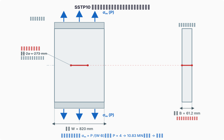
Figure 1: Geometry and loading of the SSTP10 stainless-steel wide plate. A plate 820 mm wide and 61.2 mm thick, with a transverse through-thickness crack at the weld centre (full length 2a=273 mm, red); monotonic tension is applied at the top and bottom ends, giving a membrane stress σ_m=P/(W·B). The side view on the right shows the crack penetrating the full plate thickness (through-wall) — hence there is no deepest point, and assessment is at a single front.
2. Principle and inputs
Assessment-point coordinates (Option 1):
$$ K_r = \frac{K_I^P + K_I^S}{K_{mat}} + \rho, \qquad L_r = \frac{\sigma_{ref}}{\sigma_Y} $$- Primary stress: monotonic membrane load $\sigma_m = P/(W\cdot B)$ ($W$ width, $B$ thickness).
- $K_I^P$: the stress intensity factor of the through crack (BS 7910 Annex M.3, with finite-width correction), computed by mechCalc.
- $\sigma_{ref}$ / $L_r$: Annex P net-section plastic-collapse reference stress.
- Toughness $K_{mat}$: for ductile tearing the toughness rises with the crack extension $\Delta a$, given by the J-R resistance curve (Table 13.11):
| Parameter | Value | Note |
|---|---|---|
| Crack type | through-thickness | weld centre |
| Crack half-length $a$ | 136.5 mm | full length $2a = 273$ mm |
| Plate thickness $B$ / width $W$ | 61.2 / 820 mm | |
| Base material $\sigma_Y$ / $\sigma_U$ | 234 / 594 MPa | stainless-steel base-metal properties |
| Young’s modulus $E$ / $\nu$ | 173 GPa / 0.3 | $E' = 190{,}110$ MPa |
| Primary membrane stress $\sigma_m$ | 79.7 / 206.2 / 215.8 MPa | for 4 / 10.35 / 10.83 MN |
| $K_{mat}$ (from J-R) | 145.9 / 325.2 / 532.9 MPa·m$^{0.5}$ | for $\Delta a$ = 0.2 / 2.38 / 10.94 mm |
Why base-material properties: when FITNET assesses with base-material properties all points lie above the FAL (the conservative, safe side); this is the representative basis for this test, and the one compared against here.
3. How to enter it in the calculator (using the 4 MN initiation point)
- Assessment Option (FAD): choose Option 1.
- 1. Crack / Flaw Type: set geometry to “Flat Plate” and flaw type to “through-thickness”; enter half-length $a=136.5$.
- 2. Component Geometry: thickness 61.2, width 820.
- 3. Stress: primary membrane $P_m=79.71$, bending $P_b=0$; secondary stress source “none” (see §5).
- 5. Material: yield 234, tensile 594, modulus 173.
- 6. Fracture Toughness: source “Direct $K_{mat}$”, enter 145.9 (= the J-R curve value at $\Delta a=0.2$).
- Click Run Calculation.
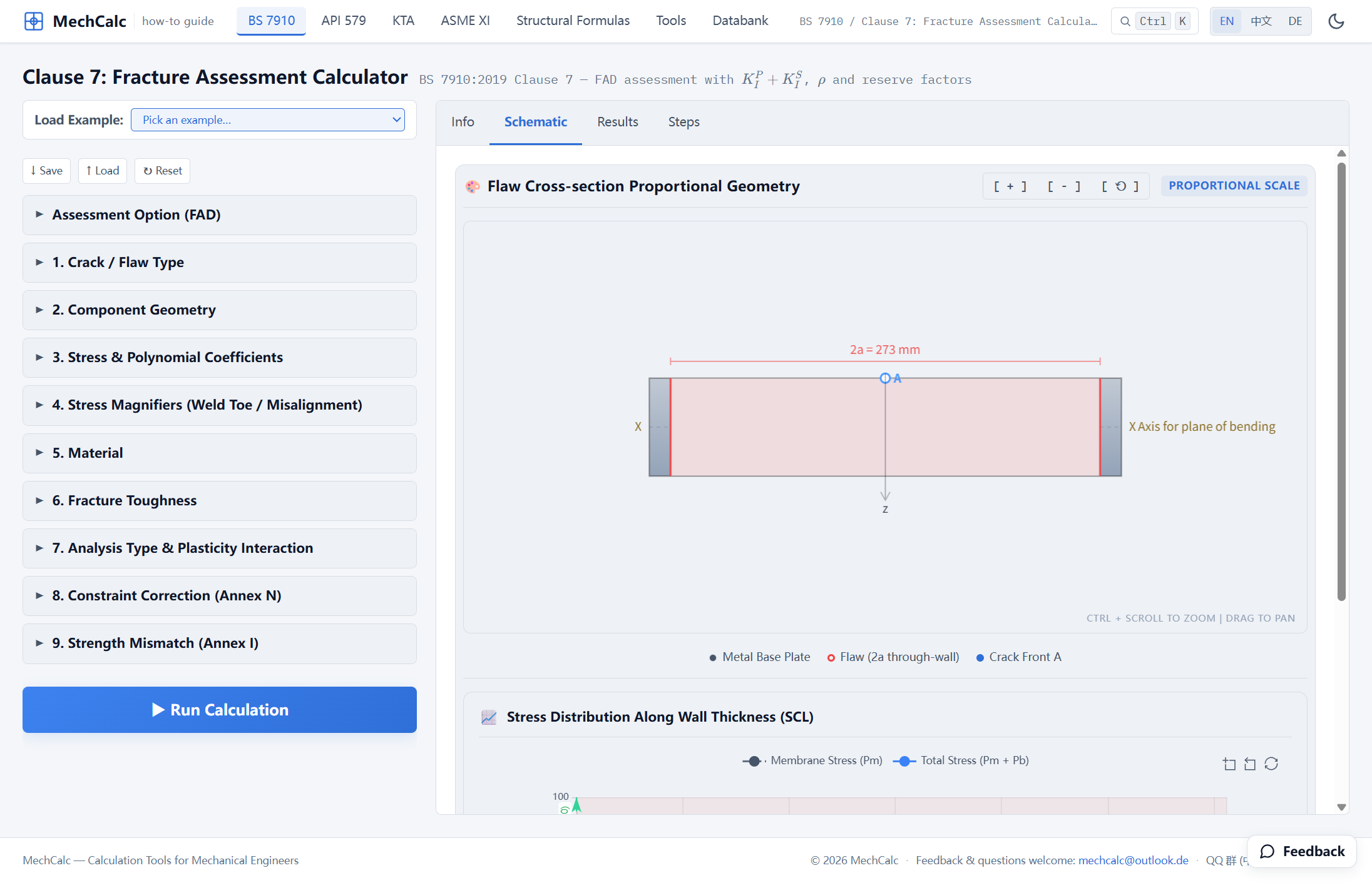
Figure 2: SSTP10 geometry in the BS 7910 Clause 7 calculator. A through-thickness crack of full length 2a=273 mm (red) on an 820 mm wide plate; crack front A spans the entire thickness — a through crack has no ‘deepest point’ and is assessed at a single front.
4. Results
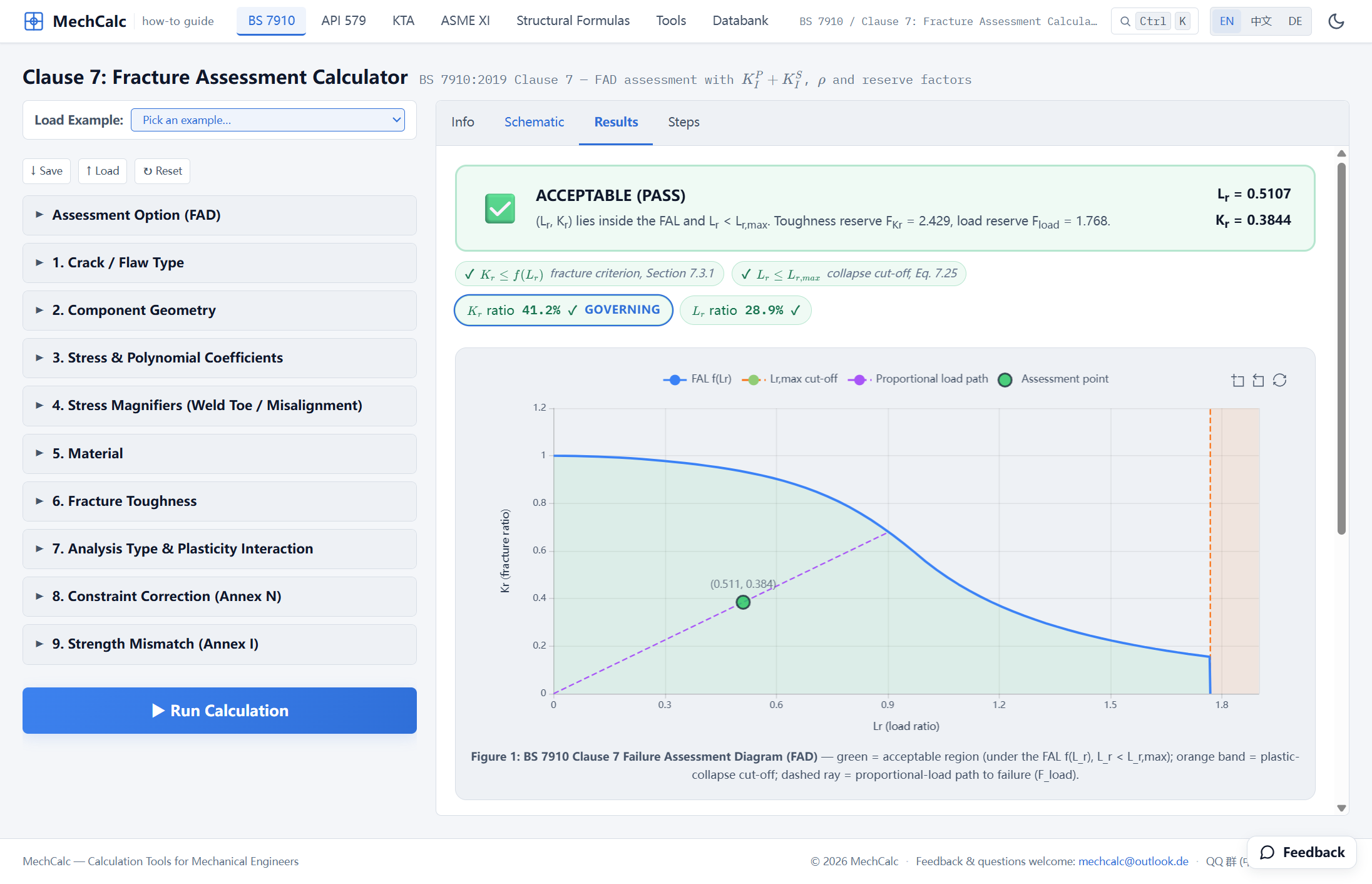
Figure 3: FAD result for the 4 MN initiation point. The assessment point (L_r, K_r)=(0.5107, 0.3844) lies inside the failure assessment line (FAL), in the green acceptable region — verdict ACCEPTABLE. Toughness reserve F_Kr=2.429, load reserve F_load=1.768; K_r utilisation 41.2%, L_r utilisation 28.9%.
The initiation point (4 MN) assembled by the engine per Clause 7:
| Quantity | Value | Source |
|---|---|---|
| Primary stress intensity factor $K_I^P$ | 56.08 MPa·m$^{0.5}$ | Annex M.3 through-crack solution |
| Reference stress $\sigma_{ref}$ | 119.5 MPa | Annex P limit load |
| Horizontal $L_r$ | 0.5107 | $\sigma_{ref}/\sigma_Y$ |
| Vertical $K_r$ | 0.3844 | $(K_I^P+0)/145.9 + 0$ |
| Verdict | acceptable (large margin) | $K_r \le f(L_r)$ and $L_r < L_{r,max}$ |
5. Cross-check against FITNET: L_r matches digit-for-digit, K_r is cross-method
Putting the three load points (base-material properties) side by side:
| Load (MN) | $\Delta a$ (mm) | $K_{mat}$ (J-R) | mechCalc $L_r$ | FITNET $L_r$ | mechCalc $K_r$ | FITNET $K_r$ |
|---|---|---|---|---|---|---|
| 4.0 (initiation) | 0.2 | 145.9 | 0.511 | 0.51 | 0.384 | 1.15 |
| 10.35 | 2.38 | 325.2 | 1.321 | 1.33 | 0.446 | 0.77 |
| 10.83 (instability) | 10.94 | 532.9 | 1.383 | 1.44 | 0.285 | 0.49 |
The horizontal coordinate $L_r$ matches FITNET almost digit-for-digit (0.511 vs 0.51, 1.321 vs 1.33, 1.383 vs 1.44, only −4% at the instability point). $L_r$ is determined only by the primary load and geometry through the Annex P limit load, so this cleanly cross-validates mechCalc’s reference-stress / limit-load implementation for the through crack, and also reproduces $K_I^P$ (56.08 MPa·m$^{0.5}$).
The vertical coordinate $K_r$ is lower than FITNET, which is an expected “cross-method” difference, not an error. Two reasons:
- The welding residual stress is not quantified. This plate carries near-yield weld-repair residual stress (tensile at the plate centre), which raises $K_r$ through $K_I^S$ — it is the main driver pushing the initiation point up to $K_r=1.15$. But the literature gives no value or profile for this residual stress (unlike the A533B example, which explicitly gave $K_I^S=46/5$), so mechCalc cannot feed it in; this post computes only the primary (membrane) side. A rough estimate is that $K_I^S \gtrsim 110$ MPa·m$^{0.5}$ would be needed to reach 1.15.
- Ductile-tearing $K_r$ uses the J route. Along the tearing locus FITNET’s $K_r$ couples the J-R curve with residual stress, which differs from the simplified “primary-side $K_I^P$ ÷ J-R toughness” basis used here.
Methodological note (DIFF is not FAIL): per the verification discipline, a difference between the same physical quantity computed by different methods is judged DIFF. Here $L_r$ is same-method (a digit-for-digit match, a positive validation); $K_r$ is cross-method and missing the residual-stress input, so only $L_r$ is compared. This agrees with the judgement on SSTP10 in the FITNET example collection.
6. An honest boundary
The A533B example could match the residual $K_I^S$ point by point because the literature gave measured residual values; for SSTP10 the literature does not quantify the residual stress, so mechCalc can only validate down to the $L_r$ level — validate firmly what can be validated, and state plainly what cannot be reproduced. This is exactly the right attitude when cross-checking a calculator against the literature: the $L_r$ line (reference stress / limit load) stands up to digit-for-digit checking, and the gap in $K_r$ is localised to the missing residual-stress input, not to the engine itself.
🧮 在线计算器:BS 7910 Clause 7 Fracture Assessment Calculator — Re-run the initiation point yourself: Option 1, through crack a=136.5, B=61.2, W=820, P_m=79.71, base material σ_Y=234/σ_U=594/E=173, K_mat=145.9, to obtain L_r=0.511, K_r=0.384, ACCEPTABLE.