🧮 在线计算器:VDI 2230 Bolted Joint Calculation — The full 14-step calculation chain (R0–R13), with six strength checks.
💡 Engineer, before blaming “poor bolt quality”, look at this real case —
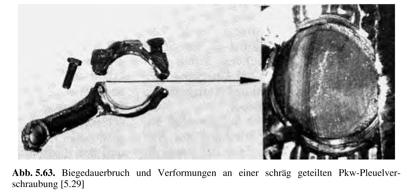
The connecting-rod bolts of a passenger-car engine failed catastrophically: the left bolt showed a typical one-sided bending fatigue fracture (a crescent-shaped fatigue region on the fracture surface), and the right bolt then broke suddenly from the force imbalance. Post-failure analysis found that the “culprit” was not the bolt material but insufficient preload. Because of assembly micro-embedding (Setzen), the preload dropped; under an eccentric service load, the connecting-rod interface opened slightly on one side, invisible to the eye (Aufklaffen), which caused a fatal alternating bending stress, finally initiating a fatigue crack at the shank root and a chain fracture.
This is exactly why VDI 2230 exists.
Why VDI 2230? — The need for systematic bolted-joint calculation
1. What is VDI 2230?
The full title of VDI 2230 is:
Systematische Berechnung hochbeanspruchter Schraubenverbindungen — Zylindrische Einschraubenverbindungen (Systematic calculation of highly stressed bolted joints — cylindrical single-bolt joints)
(VDI 2230 Blatt 1:2015-11, title page)
This standard, published by the Association of German Engineers (Verein Deutscher Ingenieure), has over 40 years of engineering use. The standard positions itself in the introduction:
“This standard, which has enjoyed practical application for over 40 years now, is a recognized and highly regarded recommendation. Throughout the world it is regarded as the standard work for calculating single-bolt joints.”
(VDI 2230:2015, Introduction, p.3)
It gives design and calculation engineers a systematic step-by-step calculation method (Rechenschritte), so that a bolted joint can be designed for functional reliability and operational safety while fully using the bolt’s load capacity.
2. Why is a simple strength check not enough?
Many engineers habitually check only “will the bolt be pulled apart” in bolt design — verifying $\sigma \leq R_{p0.2}$. But the existence of VDI 2230 shows this is far from enough. The standard clearly lists all the factors affecting bolted-joint reliability in §4.2 (VDI 2230:2015, §4.2, Bild 5).
2.1 Preload changes
The preload $F_M$ applied at assembly changes during operation. The standard gives two main reasons in §5.4.2 (VDI 2230:2015, §5.4.2):
- Embedding loss $F_Z$ (Setzbetrag): microscopic roughness is plastically flattened under load, causing an irreversible preload loss. Reference values for embedding are in VDI 2230 Table 5, with the bolt head, nut and interface each contributing about 3 μm (VDI 2230:2015, Table 5).
- Thermal expansion difference $\Delta F'_{Vth}$: when the thermal expansion coefficient or temperature rise of the bolt and the clamped parts differ, a temperature change alters the preload (VDI 2230:2015, Eq. R4/2).
2.2 The external force is not carried entirely by the bolt
This is VDI 2230’s core physical insight. The standard sets up a spring model (Federmodell) in §3.2:
“In this model, the bolt and the clamped parts are considered as tension and compression springs with the elastic resiliences $\delta_S$ and $\delta_P$.”
(VDI 2230:2015, §3.2, p.20)
The external axial force $F_A$ under service is split into two parts: the additional $F_{SA}$ on the bolt and the unloading $F_{PA}$ of the clamped parts. For the concentric symmetric case (VDI 2230:2015, §3.2.1, Eq. 8):
$$ F_{SA} = n \cdot \frac{\delta_P}{\delta_P + \delta_S} \cdot F_A $$The force ratio $\Phi = F_{SA} / F_A$ is usually far below 1.0 — the bolt actually carries only a small part of the external force. Ignoring this effect makes the design either too conservative or the preload badly set.
Deeper still: the position of the load introduction point matters just as much. VDI 2230 introduces the load introduction factor $n$ (Krafteinleitungsfaktor) to describe where the external load acts inside the clamped parts (VDI 2230:2015, §3.2.2). The closer the load acts to the interface (smaller $n$), the smaller the additional service load $F_{SA}$ on the bolt. This explains a counter-intuitive engineering practice: thickening the flange not only raises stiffness but also lowers the bolt’s dynamic loading.
2.3 The tightening method has scatter in accuracy
For the same tightening torque, due to friction-coefficient variation and tool accuracy limits, the actual preload varies between $F_{M\min}$ and $F_{M\max}$. The standard quantifies this scatter with the tightening factor $\alpha_A$ (VDI 2230:2015, §5.4.3, Eq. R1/1):
$$ \alpha_A = \frac{F_{M\max}}{F_{M\min}} $$$\alpha_A$ differs greatly among tightening methods, more than most engineers expect (VDI 2230:2015, Table A8):
| Tightening method | $\alpha_A$ reference | Preload scatter |
|---|---|---|
| Pneumatic/electric impact wrench (Schlagschrauber) | 2.5 – 4.0 | ±40% – ±60% |
| Ordinary torque wrench (Drehmomentschlüssel) | 1.6 – 1.8 | ≈ ±22% |
| Yield-point / angle-controlled (streckgrenzgesteuert) | ≈ 1.0 | ±8% |
⚠️ A key insight: even with a high-end measuring torque wrench of ±10% accuracy, the natural ±20% variation of the thread and bearing-surface friction coefficient still makes the final preload scatter about ±22%. No matter how accurate the tool, it cannot remove the uncertainty of the friction coefficient. The yield-point-controlled method takes tightening into the material’s plastic yield plateau, so friction variation barely affects the final axial force, the scatter drops to ±8%, and 100% of the material’s load potential can be used.
2.4 Interface opening: the precursor of bolt fatigue fracture (Abhebegrenze)
Ideal concentric loading is extremely rare in engineering. When the external tension or moment is off the bolt axis, the two sides of the interface are unequally loaded. VDI 2230 pays great attention to the interface opening limit (Abhebegrenze) (VDI 2230:2015, §5.2.1) — once an eccentric service load causes local opening of the interface (Klaffen), the system stiffness changes sharply, and the additional tension and bending stress on the bolt rise steeply and nonlinearly. Interface opening is exactly the root trigger of the connecting-rod bolt fatigue fracture at the start of this article. The standard’s calculation of the eccentricity $a$ and the symmetric-axis distance $s_{sym}$ is precisely to hold this critical red line (VDI 2230:2015, §5.2.1, Fig. 18).
3. The 14-step VDI 2230 calculation chain
The standard provides a 14-step calculation chain R0–R13 (VDI 2230:2015, §4.1), covering the full flow from selection to verification:
| Step | Content | Output |
|---|---|---|
| R0 | preliminary nominal diameter and limit check | $d$, $G$ |
| R1 | tightening factor | $\alpha_A$ |
| R2 | minimum required clamping force | $F_{Kerf}$ |
| R3 | external-force distribution and force ratio | $F_{SA}$, $F_{PA}$, $\Phi$ |
| R4 | preload change | $F_Z$, $\Delta F'_{Vth}$ |
| R5 | minimum assembly preload | $F_{M\min}$ |
| R6 | maximum assembly preload | $F_{M\max}$ |
| R7 | assembly stress check | $\sigma_{red,M}$, $F_{Mzul}$ |
| R8 | service stress check | $\sigma_{red,B}$, $S_F$ |
| R9 | fatigue stress check | $\sigma_a$, $S_D$ |
| R10 | bearing pressure check | $p_{\max}$, $S_P$ |
| R11 | minimum length of engagement | $m_{eff\min}$ |
| R12 | slip and shear safety | $S_G$ |
| R13 | tightening torque | $M_A$ |
4. The main equation: one formula that governs it all
The steps above finally converge to VDI 2230’s main equation (VDI 2230:2015, §4.2, Eq. 16):
$$ F_{M\max} = \alpha_A \cdot \left[ F_{Kerf} + (1 - \Phi) \cdot F_A + F_Z + \Delta F'_{Vth} \right] $$The standard positions this formula:
“All of these factors (Figure 5) are an integral part of the main dimensioning formula, which is the basis for the bolt calculation.”
(VDI 2230:2015, §4.2, p.30)
The physical meaning of each term:
| Term | Meaning | Source step |
|---|---|---|
| $F_{Kerf}$ | minimum clamping force required for function | R2 |
| $(1-\Phi) \cdot F_A$ | unloading effect of the external force on the interface | R3 |
| $F_Z$ | preload loss due to embedding | R4 |
| $\Delta F'_{Vth}$ | preload change due to thermal expansion difference | R4 |
| $\alpha_A$ | scatter amplification factor of the tightening method | R1 |
The design logic: start from the interface’s functional requirement $F_{Kerf}$, add the external-force effect and the various preload losses term by term, then multiply by the tightening scatter, to back out the maximum preload that must be applied at assembly — then verify through R7–R12 whether the bolt can carry it.
5. VDI 2230 and simplified pre-selection
In this series’ Preliminary Selection Estimate we introduced a fast pre-selection method based on the Kübler equation. Their relationship is coarse screen → precise calculation:
| Dimension | Kübler pre-selection | Full VDI 2230 calculation |
|---|---|---|
| Resilience model | equivalent hollow cylinder | cone + variable angle + multi-layer plates (§5.1.2) |
| Preload loss | fixed empirical value $f_Z$ | summed by contact-surface type + thermal correction (§5.4.2) |
| Strength checks | 1–2 | 6 (R7–R12) |
| Accuracy | ±15–20% | about ±5% (cone-angle formula, §5.1.2.1) |
The standard itself is clear-eyed about accuracy and verification:
“This standard does not in principle do away with the need for experimental and/or numerical (FEM) tests for verifying the calculation results. These are particularly advisable in the case of critical joints.”
(VDI 2230:2015, §1, p.5)
📌 The standard’s positioning in one line: if you are building a bridge (Eurocode 3 / DIN EN 1993-1-8) you care whether the bolt group resists shear failure; if you are making a pressure vessel (AD 2000-B7) you care whether the sealing gasket leaks; but if you are designing an engine connecting rod or a heavy gearbox (VDI 2230), you must, like a surgeon, use the “joint diagram” to dissect every micron of deformation precisely, compute the bolt’s fatigue limit under alternating load, and use every bit of the material’s load potential.
Data basis and accuracy statement
All formulas, values and quotations in this article are from VDI 2230 Blatt 1:2015-11. Citation format: (VDI 2230:2015, section, formula/figure/table/page).
Disclaimer: This article is for engineering teaching reference only. The final responsibility for engineering safety verification rests with the user.
📚 Series navigation
← Previous: Preliminary Selection Estimate | Next: Scope and Positioning →