This article explains how to use the seven-step method of the KTA 3206 standard for a Leak-Before-Break (LBB) analysis of nuclear piping. It pairs with the KTA 3206 LBB Pipe Analysis module of the online calculator, taking you from theory to practice.
🧮 Try the calculator now: open the KTA 3206 LBB pipe analysis calculator , choose “Fracture Mechanics → KTA 3206 LBB Pipe Analysis”, and enter the parameters to get results with a detailed formula derivation and visual charts.
1. What is KTA 3206?
KTA 3206 (full title: “Nachweise zum Bruchausschluss für drucktragende Komponenten in Kernkraftwerken”) is the German nuclear-safety standard for demonstrating break exclusion (Bruchausschluss) of pressure-bearing components in nuclear power plants.
Core idea
Unlike the US NRC LBB analysis (SRP 3.6.3), KTA 3206 is not only an analysis method but a whole integrity concept (Integritätskonzept), built on three pillars:
| Pillar | Content | Purpose |
|---|---|---|
| Basic quality | design, material selection, fabrication | ensure component quality from the source |
| In-service quality | water chemistry, operational monitoring, periodic inspection | ensure the quality does not degrade |
| Fracture-mechanics demonstration | the seven-step / six-step analysis | mathematically prove that fracture cannot occur |
Key differences from SRP 3.6.3
| Item | KTA 3206 | SRP 3.6.3 |
|---|---|---|
| Goal | exclude fracture itself | prove the crack leaks first |
| Preconditions | strictly exclude SCC, water hammer | screening filter |
| Crack growth | includes fatigue growth analysis | not included |
| Safety margin | verified in steps 6/7 | leak rate ×10, crack ×2 |
2. Four preconditions
Before any calculation, KTA 3206 requires the following preconditions. If any one is not met, the break-exclusion demonstration must not proceed.
- Exclude stress corrosion cracking (SCC/DRK): through material selection and water-chemistry control.
- Exclude relevant vibration: especially high-frequency fatigue vibration.
- Exclude non-design dynamic loads: such as water hammer.
- Sufficient material toughness: must lie in the upper shelf region.
3. The seven-step method for piping in detail
KTA 3206 Annex A defines the seven-step method for break exclusion of piping. Here is each step in detail:
Step 1: determine the initial crack (a_a, 2c_a)
   ↓
Step 2: fatigue crack growth → end-of-life crack (a_e, 2c_e)
   ↓
Step 3: critical length of a through-wall crack 2c_krit (limit load method)
   ↓
Step 4: critical depth of a semi-elliptical crack a_krit(2c_e)
   ↓
Step 5: detectable crack length 2c_LÜS (leak-rate calculation)
   ↓
Step 6: allowable crack size verification
   ↓
Step 7: final LBB verdict
Step 1: initial crack assumption
KTA 3206 sets the enveloping initial crack from the material type and wall thickness $s$:
Austenitic steel (Eq. A 2-1, A 2-2):
$$ a_a = \begin{cases} 0.3s & \text{if } s < 25\text{ mm} \\\\ 0.2s & \text{if } s \geq 50\text{ mm} \end{cases} $$Ferritic steel (Eq. A 2-3, A 2-4):
$$ a_a = \begin{cases} 0.2s & \text{if } s < 25\text{ mm} \\\\ 0.1s & \text{if } s \geq 50\text{ mm} \end{cases} $$The crack length is fixed at: $2c_a \geq 6 \times a_a$ (Eq. A 2-5)
💡 Why is austenitic more conservative? Because austenitic stainless steel is more prone to fabrication weld flaws (hot cracks, penetrating IG cracks).
Step 2: fatigue crack growth
Use the Paris-Erdogan equation to compute crack growth over the service life:
$$ \frac{da}{dN} = C \cdot (\Delta K)^m $$The main considerations:
- the normal operating transient load spectrum;
- environmental effects (especially for austenitic steel in a PWR environment, NUREG/CR-6176);
- the effect of residual stress.
The end-of-life crack $a_e, 2c_e$ feeds into the later steps.
Step 3: critical length of a through-wall crack (the core of this calculator)
Per KTA 3206 Annex B2 (limit load method), different critical failure models are set out by crack orientation (longitudinal / circumferential) and pipe type (straight / bent), covering through-wall cracks (for step 3) and surface cracks (for step 4):
1. Longitudinal crack under internal pressure (Längsriss)
This covers longitudinal cracking of the pipe under internal pressure only (hoop stress dominant):
- Straight-pipe through-wall crack (Eq. B 2.1-7, B 2.1-3): critical failure pressure: $$ p_V = \frac{2 \cdot s}{D_i} \cdot \frac{\sigma_f}{M_t} $$ with the bulging factor $M_t = \sqrt{1 + 1.61 \cdot \left(\frac{c^2}{r_m \cdot s}\right)}$.
- Straight-pipe surface crack (Eq. B 2.1-8, B 2.1-5): for the critical surface-crack depth $a_\mathrm{krit}$: $$ p_V = \frac{2 \cdot s}{D_i} \cdot \frac{\sigma_f}{M_p} $$ with the surface-crack factor $M_p = \frac{1 - \left(\frac{a}{s \cdot M_t}\right)}{1 - \left(\frac{a}{s}\right)}$.
- Bent-pipe crack (see B 2.1.2.2): uses the same formula model as the straight pipe, but the actual maximum hoop stress of the bend (per KTA 3201.2) must replace the pure-internal-pressure hoop stress.
2. Circumferential crack in a straight pipe under internal pressure and external moment (Umfangsriss)
For circumferential cracking including the overall internal-pressure axial force and moment, the standard gives two main limit-load methods:
A. PGL method (plastic limit load method)
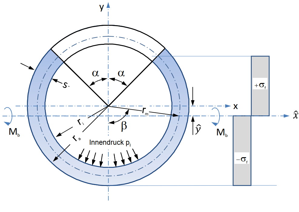
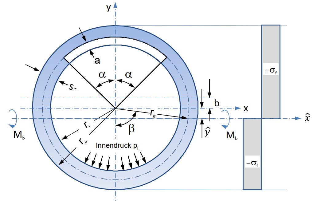
The PGL method assumes the whole wall thickness is at the plastic flow stress $\sigma_f$, and is the most conservative. For both through-wall and surface cracks it builds the critical-angle equation the same way (Eq. B 2.1-13):
$$ \frac{\pi}{4} \cdot \frac{\sigma_{ax,M}}{\sigma_f} - \cos\left(\frac{a}{s} \cdot \frac{\alpha}{2} + \frac{\pi}{2} \cdot \frac{\sigma_{ax,p}}{\sigma_f}\right) + \frac{1}{2} \cdot \frac{a}{s} \cdot \sin(\alpha) = 0 $$where:
- $\alpha$: crack half-angle [rad]
- $a/s$: take $a/s = 1.0$ for a through-wall crack (the equation then simplifies), and the actual depth ratio for a surface crack
- $\sigma_{ax,p} = p / [(D_a/D_i)^2 - 1]$: internal-pressure axial stress (Eq. B 2.1-14)
- $\sigma_{ax,M} = M / W$: moment axial stress (Eq. B 2.1-15)
- $\sigma_f$: flow stress (see Table B 2.1-1 below)
For a through-wall crack, after solving for the critical angle $\alpha_\mathrm{krit}$, convert to the critical length:
$$ 2c_\mathrm{krit} = 2 \cdot \alpha_\mathrm{krit} \cdot r_m $$B. FSK method (flow-stress-concept method)
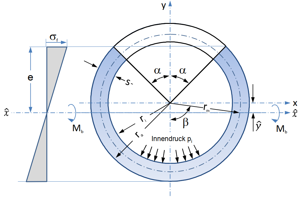
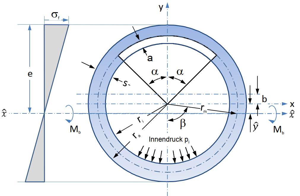
It introduces a local-yield concept, with two branches:
- FSK/MPA method: for a through-wall crack (Eq. B 2.1-17): $$ M_V = \frac{I_{\hat{x}}}{e} \cdot \left[ \sigma_f - \frac{A_0}{A_q - A_f} \cdot p_i \right] - \hat{y} \cdot A_0 \cdot p_i $$ for a surface crack (Eq. B 2.1-18): $$ M_V = \frac{I_{\hat{x}}}{e} \cdot \left[ \sigma_f - \frac{A_w}{A_q - A_f} \cdot p_i \right] - (\hat{y} + b) \cdot A_w \cdot p_i $$ it rigorously accounts for the neutral-axis shift $e$ and the remaining-section parameters to derive the bending limit load.
- FSK/KWU method (Eq. B 2.1-20, 21): defines the stress magnification factors $k_a, k_b$ so that the local effective stress $\sigma_\mathrm{eff}$ at the crack tip reaches the flow stress: $$ \sigma_\mathrm{eff} = k_a \cdot \sigma_{ax,p} + k_b \cdot \sigma_{ax,M} = \sigma_f $$
The value of the flow stress $\sigma_f$ (Table B 2.1-1)
| Method | Austenitic steel | Ferritic steel |
|---|---|---|
| PGL | $(R_{p0.2} + R_m) / 2.4$ | $R_{p0.2}$ |
| FSK/MPA | $R_m$ | $(R_{p0.2} + R_m) / 2$ |
| FSK/KWU | $(R_{p0.2} + R_m) / 2$ | $R_m$ |
⚠️ PGL is the most conservative, because it uses the lowest flow stress and gives the shortest critical crack length. PGL is the recommended first choice.
Step 4: critical depth of a surface crack
From the end-of-life surface-crack length $2c_e$ found in step 2, compute the critical surface-crack depth $a_\mathrm{krit}(2c_e)$ that can still carry all occurring loads (operating and accident) at that length. In essence this again uses the limit load method of step 3 (the PGL or FSK straight-/bent-pipe formulas) for surface-crack failure: fixing the crack length at $2c_e$, back-solve for the maximum depth $a$ that causes section or local failure. This depth is an important input to the later steps.
Step 5: detectable crack length (leak-rate calculation)
To meet the core LBB definition, you must show that when a through-wall crack occurs, it produces enough leakage to be found by the monitoring system before reaching the critical length (Leak-Before-Break). The procedure:
- Determine the monitoring capability: the minimum leakage mass flow $\dot{m}_\mathrm{L\ddot{U}S,det}$ that the leak-monitoring system (LÜS) can reliably detect.
- Set the intervention limit: with the operating manual (BHB), set the leak-rate limit $\dot{m}_\mathrm{L\ddot{U}S,BHB} \geq \dot{m}_\mathrm{L\ddot{U}S,det}$ that triggers intervention (leak search, shutdown).
- Compute the detectable length: accounting for friction, flashing and surface roughness of the fluid in the crack (e.g. using the Pana or Moody model), find the through-wall crack length that at normal operating pressure produces exactly that intervention leak rate, and define it as the detectable crack length $2c_\mathrm{L\ddot{U}S}$.
Step 6: allowable crack size verification
- Allowable crack depth: $a_\mathrm{zul} = \min(0.75 \times s,\ a_\mathrm{krit}(2c_e))$ (Eq. A 2-10)
- Allowable crack length: $2c_\mathrm{zul} = 2c_\mathrm{krit} - \Delta 2c_\mathrm{WKP}$ (Eq. A 2-11)
Verification conditions:
$$ a_e \leq a_\mathrm{zul}, \quad 2c_e \leq 2c_\mathrm{zul} $$Step 7: final LBB verdict
If the pipe needs an LBB demonstration (i.e. no pipe whip restraint is fitted), you also need:
$$ 2c_\mathrm{LÜS} < 2c_\mathrm{zul} $$where $2c_\mathrm{LÜS}$ is the detectable crack length from the leak-rate calculation.
4. Worked example: austenitic pipe
The following data are from KTA 3206 Annex D1, to demonstrate the full analysis flow.
Input data
| Parameter | Symbol | Value | Unit |
|---|---|---|---|
| Inner diameter | $D_i$ | 243 | mm |
| Wall thickness | $s$ | 15 | mm |
| Material | — | X6 CrNiNb 18 10 (1.4550) | — |
| Yield strength | $R_{p0.2T}$ | 167 | MPa |
| Tensile strength | $R_{mT}$ | 409 | MPa |
| Elastic modulus | $E$ | 186,000 | MPa |
| Internal pressure | $p$ | 7.4 | MPa |
| Bending moment | $M$ | 72.3 × 10⁶ | N·mm |
Analysis results
| Step | Parameter | Result |
|---|---|---|
| Step 1 | initial crack | $a_a = 4.5$ mm, $2c_a = 27$ mm |
| Step 2 | end-of-life crack | $a_e = 4.78$ mm, $2c_e = 28.1$ mm |
| Step 3 (PGL) | flow stress | $\sigma_f = 240$ MPa |
| Step 3 (PGL) | critical crack length | $2c_\mathrm{krit} = 273.9$ mm |
| Step 6 | allowable crack depth | $a_\mathrm{zul} = 11.25$ mm |
| Step 6 | allowable crack length | $2c_\mathrm{zul} = 271.9$ mm |
| Step 7 | LBB safety margin | $271.9 / 60 = 4.5$ ✅ |
Conclusion: break exclusion holds. The allowable crack length (271.9 mm) is far larger than the detectable crack length (60 mm), a margin of over 4.5.
Using it in MechCalc
- Open the MechCalc calculator .
- Choose “KTA 3206 LBB Pipe Analysis”.
- Enter the parameters from the table above.
- Click “Calculate”.
- Review the detailed results and the verdict.
5. Special considerations for ferritic piping
The main differences between ferritic and austenitic piping:
- Smaller initial crack ($0.2s$ vs $0.3s$): ferritic steel has better weld quality.
- Higher yield strength: so the PGL flow stress $\sigma_f = R_{p0.2}$ is larger.
- Toughness verification: the operating temperature must be confirmed to be in the upper shelf region.
- Environmental effects: not affected by PWR-water acceleration.
6. Summary
The seven-step method of KTA 3206 provides a systematic, repeatable analysis framework for break exclusion of nuclear piping. Its core logic:
- assume the worst initial crack (a conservative assumption);
- let the crack “run” a full life under load (fatigue growth);
- compute “how long a crack the pipe can carry” (limit load method);
- verify the crack has ample safety margin (allowable crack size and LBB).
Only when all steps pass can break exclusion be declared.
📖 Reference standard: KTA 3206 (2014-11) — Bruchausschluss für drucktragende Komponenten in Kernkraftwerken